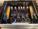
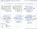
I’m building a switch box to do A/B comparisons between two amplifiers as well as two preamps. I’m including a schematic of the relay contact assignments of the relays that handle the audio signals that I am routing through the device. The two selector relays (3 and 4) are turned on/off remotely from two different remote control units. At this point I have the preamp relays (4 and 5) wired up and switching properly from its remote unit. The signal path is correct and I am able to switch between two preamps, but there is a loud pop each time signal relay (5) turns on or off. I’ve measured the spike and it ranges from 50mv to just under 200mv and lasts 250-300ms. These spikes aren’t enough to harm a speaker but they are quite unpleasant.
I have 1N4148 flyback diodes across the 12v voltage input pins of the relay, but I’ve actually tested for the surge without the diodes and it is about the same. My best guess is that voltage from the switching pins is able to jump to the signal pins. I would have thought that they would be well isolated. I’ve tried installing .5uF caps across all the connections (power and signal) but hasn’t helped.
Is there any way to fix this problem?
Is the problem that 12v relays are too high powered for my application? I haven’t found any 5v 4PDT relays in the format that I’m using now. Low power relays signal relays could potentially work, but that would completely change the design and scope of the project.
I’m attaching a schematic of the relays and a couple of photos of my build so far. Thanks, in advance, for your help!


