Continue to Site

Welcome to our site!

Electro Tech is an online community (with over 170,000 members) who enjoy talking about and building electronic circuits, projects and gadgets. To participate you need to register. Registration is free. Click here to register now.

  • Welcome to our site! Electro Tech is an online community (with over 170,000 members) who enjoy talking about and building electronic circuits, projects and gadgets. To participate you need to register. Registration is free. Click here to register now.

Does 4R7 = 4.7 ohms?

Status
Not open for further replies.

gary350

Well-Known Member
I think 4R7 is 4.7 ohms but I forgot.??? See resistor top right connected to the speaker. I may need to order this. Two 10 ohm in parallel might ohm out very near 4.7 ohms. Speaker is 8 ohms but ear phone work best.

I have not checked data sheet yet I hope someone knows from memory if NE4558 can be swapped with TL072 and not need to change resistor or cap values? I already have TL047 OP.

Online say transistor A1015 is PNP and another place says NPN and a 3rd place says 2N2907 ????

Online say transistor C1815 is 2N2907. ??? What is the truth???


MetalDector.jpg
 
Yes. The multiplier letter can be used in place of the decimal point, with R being x1, like 4.7R

Putting DC through a speaker like that is not a particularly good idea, though probably its OK for a crude noisemaker..
 
Online say transistor A1015 is PNP and another place says NPN and a 3rd place says 2N2907 ????

Online say transistor C1815 is 2N2907. ??? What is the truth???
Not sure of the datasheet, but transistors are not critical. You can select for your current draw needs.
 
A1015 is drawn as a PNP, which makes sense considering the rest of the components. A 2N2907 is a PNP transistor. As Lightium says, almost any PNP transistors will do.

C1815 is drawn as an NPN transistors which makes sense in the circuit. A PNP would not work as well there but the circuit values there are so non-critical that a PNP might be adequate. It would be using the emitter as the collector and vice-versa which is bad practice and the gain is terrible like that, but it could work.
 
For the truth you would need to ask the person who drew the schematic. As others have said approximations to the truth may also work. There may also be cases where this will not happen.
 
I have a 4.7 ohm resistor but its 5 watts. LOL

It took a while but I finally learned, A1015 is PNP and is a general purpose transistor = to 2N3906.

I also learned C1815 is NPN and is a general purpose transistor = to 2N3904

This is good, I already have 2N3904 and 2N3906 and 1N4118 diodes and TL072 and 555 and most of the resistors and capacitors.
 
Last edited:
That Metal detector circuit is rather crude & the principle used will not detect small objects at any distance, especially underground.

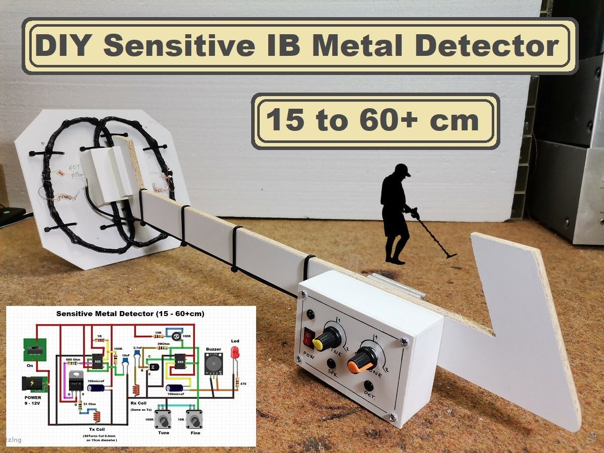
An induction balance type should give rather better results and is not all that more complex - there are a couple of design articles here:

A basic one:

An older but slightly more sophisticated version:

I have decided to build the metal detector in the first link. I redrew the circuit drawing so it is easier to build. I'm not sure what variable resistor 100K does that is connected to the NPN transistor. They claim any general purpose transistor & general purpose mosfet will work. I'm not sure what the buzzer is? I wonder if a microwave oven buzzer will work. I would rather have an ear phone than buzzer.

100_7578.JPG
 
Last edited:
Try connecting headphones (with a series limiting resistor to set a reasonable volume) in place of the "buzzer"? As it's AC coupled, it seems unlikely is it a buzzer with electronics, more likely a miniature speaker.

The upper 100K pot sets a switching threshold balanced against the low DC bias current of the transistor, from the look of it.

The instructions say to set it to 90K to start off with.

The coil on that style is very critical - wind the two identical coils then make the "head" using some rigid plastic so it's all waterproof once finally assembled.

When I built one some decades ago, I started with the coils lightly taped down then started putting blobs of epoxy on as I refined the adjustment, leaving less and less movable for fine tweaking as I went, until it was all solid.

It worked wonderfully for a day or so - but unfortunately I'd made the coil base and lid from hardboard (like 3mm fibreboard) and that absorbed moisture as I used it outdoors and messed it up!
I had varnished it, but apparently that was not adequate weatherproofing.
 
Status
Not open for further replies.

New Articles From Microcontroller Tips

Back
Top