Continue to Site

Welcome to our site!

Electro Tech is an online community (with over 170,000 members) who enjoy talking about and building electronic circuits, projects and gadgets. To participate you need to register. Registration is free. Click here to register now.

  • Welcome to our site! Electro Tech is an online community (with over 170,000 members) who enjoy talking about and building electronic circuits, projects and gadgets. To participate you need to register. Registration is free. Click here to register now.

Door Sensor project

Status
Not open for further replies.

crchisholm

New Member
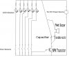
I would like some help with a project. I need to create an indicator board that will light LEDs when doors or open. One LED per door. It's a simple 12v circute with several door sensors, LEDs and resisters. I have a diagram, but I can't figure out how to upload it.

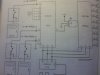
I would like to add the circuitry so that a pizo buzzer will buz for a second or two when ever one of the doors is opened. Not sure how to do it with several switch/Led/resister combinations in parrallel.
 
Last edited:
Easiest to sense a door open - close is with a magnet and a reed switch.

Mount the magnet on the door and the reed switch above the door and run the wiring in neatcap or tight along the doorframe.
 
RODALCO said:
Easiest to sense a door open - close is with a magnet and a reed switch. Mount the magnet on the door and the reed switch above the door and run the wiring in neatcap or tight along the doorframe.

That was the easy part. Since the 'door open signal' will be constant as long as the door is open you can't use a timer IC (NE555) to trigger the piezo. The NE555 is retriggerable. Instead use a one shot timer made with 1/2 CD4027 (J-K-Flip-Flop)

The values shown give a positive shot (after the inverter) of 1200ms duration. The switch position thereafter is unimportant. This circuit triggers only when the switch output goes positive.

The green LEDs in the schematic signal "door closed" and the red ones "door open". Simultaneously the output of the corresponding Flip-Flop goes high for the already mentioned duration.

Boncuk
 
Last edited:
Hi there

This took me over an hour to think of, but it was so simple (dont know what happend to me). Any way heres how the below schematic works.

1 of the buttons are pressed
light turns on
NPN transistor opens alowing current in
Capacitor fills up while a piezo buzzer sounds
Once button is let go capacitor will discharge into the piezo making it softly dim out.
Playing with the variable resistor will change how long the buzzer will sound for. Aswell as different sized capacitors will change sound duration.

Hope this helps, let me know how you went
 

Attachments

  • new circuit1.JPG
    new circuit1.JPG
    36.4 KB · Views: 185
i have this. its from a book i will upload pic tommorrow. its complete circuit
 
Thanks Rodalco -- that part I had, though.

Boncuk: This is the direction I was looking for. Two questions though....
1) Door SW1 is opened and the LED lights and buzzer sounds. Door is left open. Door SW2 is opened. Will this circuit still fire the piezo for door SW2?

2) The part I didn't say is that I have 24 rooms to put these indicators on. Each room has four or five doors. So I am talking probably a 100 or more doors. Do you think this method will "scale up" that far? If I needed to, I might be able to join all the doors in a single room so that the LED indicated any door in that particular room, but it would probably be "cooler" if I could sense each of the doors seperately.

What do you think?
 
Spitso: I would need a piezo circuit for each door if I did it that way, wouldn't I?

SilverBlade: Thanks. I would like to see it.

Charlie
 
here it is. i took its picture from the book. since i lost the schematic i made in EWB.
 

Attachments

  • Image(240).jpg
    Image(240).jpg
    236.3 KB · Views: 257
crchisholm said:
Spitso: I would need a piezo circuit for each door if I did it that way, wouldn't I?


No only one piezo buzzer will be required, due to all the open switches are joined together therefore if any switch is closed, than current will flow through the base of the transistor.

Hope this helps. message me with your results
 
So just checking up. How did you go on building the electronic circuit? Was my schematic used? was it succesful?

Thanks Spitso
 
Status
Not open for further replies.

Latest threads

New Articles From Microcontroller Tips

Back
Top