aeroboy049
New Member
Respected all,
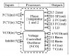
I am still new to electronics and am currently refering the book "Electronic circuits for Evil Genius" by Dave Cutcher.In lesson 34 he introduced the concept of clock signals and generating them by using 4046 IC by using only the VCO part of it.When I tried out the schematic given in the book(which I have attached alongwith) on the breadboard ,it didn't work.Then I tried to simulate the same in Proteus.
There too,it wasn't working the way it way given in the book.As per the book:
1)As soon as the push button is pressed, the LED should be flashing so fast so that you are unable to tell whether the LED is on/off.
2)Gradually the rate of flashing should slow down.
3)And finally it slows down to snails pace to a final halt.
When I assembled the circuit on the breadboard,and pressed the push button;the LED didn't lit up at all.
As far as simulating in Proteus is concerned,it shows LED flashing even before the switch is pressed.
And after that too,using oscilloscope,it is unable to show any difference.Infact the left part of the circuit using the zener diode and RC ckt,which is producing a gradually reducing voltage pulse;just does show any change in the voltmeter.Though when i disconnect it from pin9(VCO in) it does seem working alright.Then I tried to reduce the value of resistance in this ckt from 10M to 1K and the pulse was now noticeable in the voltmeter as well as in the oscilloscope there was a variation shown that of decreasing frequency of the square wave output at pin3(VCO out).But still it didnt come to a final halt and the LED again started to blink.
Please tell me what is wrong in my implementation.
Actually the next 5 lessons all include this VCO for clock input.Plz help me so that I can get on with things ahead.
Attachments
Last edited:
