Continue to Site

Welcome to our site!

Electro Tech is an online community (with over 170,000 members) who enjoy talking about and building electronic circuits, projects and gadgets. To participate you need to register. Registration is free. Click here to register now.

  • Welcome to our site! Electro Tech is an online community (with over 170,000 members) who enjoy talking about and building electronic circuits, projects and gadgets. To participate you need to register. Registration is free. Click here to register now.

Dr. Mike & crew - Hall circuit works perfectly! Now trying to understand it --

Status
Not open for further replies.

scaecrow

New Member
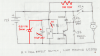
Trying to make sure that the components used are well within spec but I am having a little trouble trying to identify the voltages and current in the circuit and also with the data sheets. When the zener reaches threshold, will it handle the current with the 330 limiting res in series with it? Would a larger cap provide a better buffer? By decreasing the biasing resistor to 1.330k, will the npn handle it?

Thankx in advance for any smart folks that want to spend any time on this - This circuit works with stuff I had - 1n4004, 7.5v zener, 390 ohm r, and I forgot to reduce the 2k r to 1k.
Again, Thankx,
Glenn
 

Attachments

  • hall effect cicuit.png
    hall effect cicuit.png
    383.6 KB · Views: 235
I remember when Mike helped you with this and was going to ask then and forgot to ask. Something I don't get or am missing is how the hall effect switch even works. The power for the hall effect is set up using your zener in series with the 330Ω resistor. However as drawn the the power for all of that comes from the normally open side of K1A contacts. With the relay contacts open how is the Hall effect powered? I see the 1KΩ pull up at the hall output, I see the Hall driving the 2N2222 with its output, I see how S1 works to override. I just don't see how the hall effect does anything with K1A open?

Ron
 
Last edited:
Ron,

The Hall Effect is only used to unlatch the relay, and doesn't need to be powered after that. S1 Latches the relay, and powers the Hall.

ScaeCrow,

which component are you worried about? The Zener?
 
Last edited:
Dr. Mike - Actually all components. I was trying to compare what I thought the perameters might be to the data sheets. I don't know what the reverse current is so I can choose the right 6.8v 1 w zener. What is the collector (K1) current with the manual switch off? power rating choices are between 300 - 625 mw. Is the cap the best choice? Maybe I should use a meter (!) on the circuit I have now. What a concept!
 

Attachments

  • hall effect cicuit.png
    hall effect cicuit.png
    383.6 KB · Views: 160
Last edited:
Well, you can measure the voltages and currents in the actual circuit, calculate what they would be using formulas, or use an analog simulator to see if everything is within limits.
 
Thanks Mike. Never thought of it that way.

Much Appreciated
Ron
 
Status
Not open for further replies.

New Articles From Microcontroller Tips

Back
Top