Continue to Site

Welcome to our site!

Electro Tech is an online community (with over 170,000 members) who enjoy talking about and building electronic circuits, projects and gadgets. To participate you need to register. Registration is free. Click here to register now.

  • Welcome to our site! Electro Tech is an online community (with over 170,000 members) who enjoy talking about and building electronic circuits, projects and gadgets. To participate you need to register. Registration is free. Click here to register now.

drive circuit for IR sensor

Status
Not open for further replies.

baftab

New Member
hey
i am working on a project and i need to connect at89c51 interrupt to an ir sensor

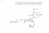
my ir sensor has an output of 2 v, when its nc
when its broken, its output goes to .8v

i cannot drive my controller with 2v, so made a drive circuit
i havent yet connected it to my controller
here is the schematic...tell me...is it enuff to convert 2v to 5 v??

thanks
 

Attachments

  • drive.JPG
    drive.JPG
    28.7 KB · Views: 754
Last edited:
hi,
As the signal Vmax is only 2.1V and the Vbe junction of the transistor is about 0.7V, this means the 10K series resistor has only 1.4V across it.
This gives a base current of only 0.14mA!, if the transistor has a gain of 100,the transistor will only have a collector current
in the order of 14mA, which is too low to drive a relay.

I would reduce the 10K resistor to a value of about 330R.

What is the purpose of the relay in the IR sensor circuit,
[do not connect as relay to a MCU as you have drawn it, the back emf could damage the MCU]

It would be possible to connect a 4K7 resistor in place of the relay and use the transistor collector out of 0V/+5V to drive
the MCU pin.
[the signal would be inverted, but this should be easy to correct in the program].
 
Last edited:
oh am sorry...i am not connecting a relay...
i was thinking of directly connecting the output to the mcu....the two wires tht say "to microcontroller"

i dont intend to drive a relay...wrote it wrongly in the title...

i'll change the base resistor , but the collector resistor is fine..right??
i dont intend to use a relay

is there anything else wrong??
 
baftab said:
oh am sorry...i am not connecting a relay...
i was thinking of directly connecting the output to the mcu....the two wires tht say "to microcontroller"

i dont intend to drive a relay...wrote it wrongly in the title...

i'll change the base resistor , but the collector resistor is fine..right??
i dont intend to use a relay

is there anything else wrong??

Hi,
The collector resistor is OK.
I see from your drawing that you have +6V to the top of the resistor, will your MCU accept a +6V input! or does it specify a maximum of +5V?
 
hi,
The 10K will limit the input to the MCU pin to +5V.
 
Last edited:
one thing more
using uln2803...will it work?
i mean instead of a frive circuit...can i use uln2803???
 
dear sir,
can u send me remote controller circuit for control two relayas !!
please reply me soon as possible (kasungayantha@yahoo.com)

thankyou !!
 
Status
Not open for further replies.

Latest threads

New Articles From Microcontroller Tips

Back
Top