Continue to Site

Welcome to our site!

Electro Tech is an online community (with over 170,000 members) who enjoy talking about and building electronic circuits, projects and gadgets. To participate you need to register. Registration is free. Click here to register now.

  • Welcome to our site! Electro Tech is an online community (with over 170,000 members) who enjoy talking about and building electronic circuits, projects and gadgets. To participate you need to register. Registration is free. Click here to register now.

Eagle CAD manual routing question

earckens

Member
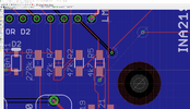
I am trying to connect the two via's that currently are connected with an airwire (see picture).

However I get a yellow X-mark on the destination via when doing a bottom trace between them.

How to properly connect a bottom trace between both via's?

Eagle v7.6.0
 

Attachments

  • lab PSU LM723 v12a.brd
    132.1 KB · Views: 8
  • pic1.png
    pic1.png
    1 MB · Views: 12
Solved:
1. starting from the upper right airwire/via trace bottom track to lower left track at R5, connect to upper trace (without via). Add via to connect lower and top trace at R5.
2. the ground polygon plane automatically will make way for that new bottom trace.
 
I was going to suggest that you need to "rebuild" (in EasyEDA terms, I've totally moved on from my old version of Eagle). Glad you figured it out.
 

New Articles From Microcontroller Tips

Back
Top