Continue to Site

Welcome to our site!

Electro Tech is an online community (with over 170,000 members) who enjoy talking about and building electronic circuits, projects and gadgets. To participate you need to register. Registration is free. Click here to register now.

  • Welcome to our site! Electro Tech is an online community (with over 170,000 members) who enjoy talking about and building electronic circuits, projects and gadgets. To participate you need to register. Registration is free. Click here to register now.

FETs instead of a relay

Status
Not open for further replies.

kinarfi

Well-Known Member
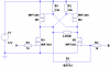
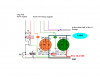
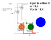
I'm using a relay to disconnect the FETs of an H Bridge from the controller inputs and would like to be able to use FETs instead of a mechanical relay. The circuit voltage is 14.4 (automotive) and the source of the disconnecting FETs would be 0 or 14.4 depending on the input to the controlled FETs. As I see it, the gates would need 24.4 applied to keep a Vgs of 10. will this work?
Kinarfi
 

Attachments

  • untitled..PNG
    untitled..PNG
    14.7 KB · Views: 207
Last edited:
What about using p-channel MOSFETs for the high side?

The disadvantage is they have a higher resistance and are slighlty more expensive but it makes the circuit easier to build.

This circuit also has a shoot through protection so if both A and B are activated the MOSFETs don't all turn on at once and short circuit.

You might need to add some additional back-EMF suppression diodes if the internal MOSFET diodes aren't good enough.
 

Attachments

  • h-bridge no shoo&#11.PNG
    h-bridge no shoo&#11.PNG
    5.7 KB · Views: 201
Last edited:
It might be easier to short the gates to the source (where your resistors are) instead of trying to block the signal. This is also one of the big advantages of using totem-pole drivers. The gate is always shorted to the source when there is no signal.

Why do you want to put a switch in anyway? Can you not just shut down the gate signal instead?
 
I have the H Bridge circuit built and operating and installed, and when the current hits 50 amps, the relay(4pdt) opens the inputs and and all 4 Power FETs turn off, the relay is a small, low current, signal relay, and works well, but I was thinking to replace it with FETs. During normal operation, the disconnecting FETs (whether P or N) will see a Vgs of about 24or 12 volt, depending on if the power FET is on or off. I'm just wondering if the FETs can handle that much gate voltage. The gate voltage is taken to ground to turn the disconnecting FETs off.
Kinarfi
 
It might be easier to short the gates to the source (where your resistors are) instead of trying to block the signal. This is also one of the big advantages of using totem-pole drivers. The gate is always shorted to the source when there is no signal.

Why do you want to put a switch in anyway? Can you not just shut down the gate signal instead?
The switch is controlled by another part of the circuit which senses current( 50 amps), and once the relay trips, the current goes away and the relay uses the gate signal to stay tripped until the signal goes away, end of travel for that motor direction.
Kinarfi
 
Very clever Hero999!
I like -a lot- your simple use of D1 to prevent simultaneous conduction.

However, for optimal shoot-thru, I would still add some dead-time transitioning from A ->B and from B->A
 
Yes, D1 won't act instantly, if B is made high, then A is made high, it will take D1 about 20ns or so to short M2's gate to 0V, meanwhile there will be a short high current pulse but it shouldn't last or long enough to damage the MOSETs which will be able to withstand surges.

I chose a fast diode - according to the datasheet the reverse recovery time of the B54 is 5ns which is faster than most MOSFETs but the gate won't discharge instantly although it should still be fast enough to prevent the current pulse being too high.

Nevertheless, D1 functions as a protective device in case of a malfunction and shouldn't be used routinely.
 
Last edited:
Nevertheless, D1 functions as a protective device in case of a malfunction and shouldn't be used routinely.

Indeed!
It should be used as a backup, in case of a main controller malfunction.

Perhaps to round-up the circuit, it would be worthwhile to add a pulldown 100k resistor from each gate to gnd, to turn the FETS off as a default.

This would be useful for instance, with microcontrollers with multifunction I/O pins, at startup they are usually configured as inputs.
 
Last edited:
It might be easier to short the gates to the source (where your resistors are) instead of trying to block the signal. This is also one of the big advantages of using totem-pole drivers. The gate is always shorted to the source when there is no signal.

Why do you want to put a switch in anyway? Can you not just shut down the gate signal instead?
smanches, thanks for the suggestion, I drew it up on paper and it looks like the way to go. Simple, easy, just had to invert the - signal with a PFET to drive the NFETs, so I end up using 3 PFETs and 2 NFETs instead of an $8.00+ relay and it's solid state and takes up a lot less room.
Thanks Again.
Kinarfi
 

Attachments

  • Post..PNG
    Post..PNG
    12.4 KB · Views: 181
Status
Not open for further replies.

Latest threads

New Articles From Microcontroller Tips

Back
Top