Continue to Site

Welcome to our site!

Electro Tech is an online community (with over 170,000 members) who enjoy talking about and building electronic circuits, projects and gadgets. To participate you need to register. Registration is free. Click here to register now.

  • Welcome to our site! Electro Tech is an online community (with over 170,000 members) who enjoy talking about and building electronic circuits, projects and gadgets. To participate you need to register. Registration is free. Click here to register now.

First Draft. :- PIC trainimg board -:

Status
Not open for further replies.

Ayne

New Member
I am new to programming and i started 2 or 3 weeks ago.
My purposes are,
1. Making a training board for beginners like me
2. Learning Eagle (i am running Eagle first time) :D .

Help,
How we connect the two terminals virtually in eagle without wire???

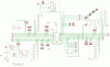
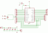
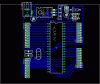
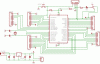
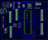
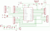
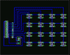
Below is the circuit, final touches remaining.

I request to experts members plz check this board and guide me??

and request to all members plz put ur reviews about board?
Thanks.
Sorry for my poor English.
 

Attachments

  • First Draft.GIF
    First Draft.GIF
    195.7 KB · Views: 362
That's a pretty large board for a first-timer! hey, at least you're ambitious, good luck with it.
Ayne said:
How we connect the two terminals virtually in eagle without wire???
to connect multiple wires "virtually" you just have to give them the same name, just use the 'Name' tool; to connect device terminals just add a short wire to each, and name the wires. It's also a very good idea to label them so that you can clearly see on the schematic the name of any wires connected in this way, using (you guessed it) the 'Label' tool.
 
I request to experts members plz check this board and guide me
Before you get too carried away, are you using the "free" version of Eagle? The free version has a max board size of 4 inches square, which looks like you'll exceed with this project/schematic.
 
Before you get too carried away, are you using the "free" version of Eagle? The free version has a max board size of 4 inches square, which looks like you'll exceed with this project/schematic.

Oh ****,
i am using free version.
really Badddddddddddd....
 
perhaps a modular design would still be possible? instead of making one big development board, is there any way you could make one main board that holds the PIC and related support circuitry, and has headers for the I/O pins, and then make separate boards with different things on them (LCD, switches, whatever) that can be plugged in. not only would it work in the free version, but it would be more flexible for future projects as you could switch out for different addon boards.

I believe this is how Nigel does his boards.
 
Modular Design

Thanks evandude.

now i am making section wise.
Below is the design of the Main Board(It's SCH & it's PCB)...

What u say about PCB???
 

Attachments

  • Only PIC SCH.GIF
    Only PIC SCH.GIF
    23.1 KB · Views: 295
  • Only PIC PCB.GIF
    Only PIC PCB.GIF
    19.9 KB · Views: 393
Just an idea! - I put a LOT of thought into my tutorial boards, to try and keep them simple, but versatile - as such I use ten pin connectors for all the ports, with the end ones being 0V and 5V. This way you only need one connector to join the boards together - and because all ports use the same size socket, you can plug the same board to different ports (bearing in mind the limitations of some ports and pins).
 
Ayne said:
What u say about PCB???

the traces in the lower left of your pcb are too close together

one trick I like to use for modular boards is to layout the most important board, which sets the size for the stack. then I save that layout under a different name, for the next board in the stack. Now I can delete some parts, and add others, while preserving the exact location of connectors and such which will be used to connect one board to another.

using metallic screw together stand-offs is a great way to move power and ground through the stack. ribbon cable and sil or dil headers work good for moving signal lines ... a dil crimp-on header lets you pair each signal line with a ground for excellent noise immunity.
 
I found One error in Nigel's board(PIC16F877A) that,
+5 Volts is direcly connected to MCLR, so we can't program it with ICD2...
Am i right???
 
Ayne said:
I found One error in Nigel's board(PIC16F877A) that,
+5 Volts is direcly connected to MCLR, so we can't program it with ICD2...
Am i right???

No, it's not an error, it's was never intended for ICSP. I've since modified a 16F876 board to add ICSP and an InchWorm socket.
 
Both are completed

Both (PCB & SCH) are completed.
A slide swith is added to test the supply or testing that the PIC is running is properly.

Connector is added for Inchworm ICD2.

Again, I request to experts members plz check this board and guide me.
 

Attachments

  • FinalPCB.GIF
    FinalPCB.GIF
    42.1 KB · Views: 177
  • FinalSCH.GIF
    FinalSCH.GIF
    46.3 KB · Views: 177
KeyPad

KeyPad module has been completed...
Where can i buy these switches??? and what is the name of these switches???

Help needed from Eagle users.
How can i print only traces for toner transfer method???
 

Attachments

  • KeypadSCH.GIF
    KeypadSCH.GIF
    18 KB · Views: 157
  • KeypadPCB.GIF
    KeypadPCB.GIF
    30.1 KB · Views: 157
Ayne said:
How can i print only traces for toner transfer method???
All you need to do is hide the unwanted layers first.
 
Status
Not open for further replies.

Latest threads

New Articles From Microcontroller Tips

Back
Top