captainate
Member
Hey all,
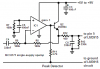
I'm trying to adapt a circuit for a basic ~27 dB boost intended for use in a guitar pedal. I would like to build it, with these modifications: on/off LED (easy), and 5 LED VU meter, which reads the OUTPUT (post-boost effect) at a reasonable level (highest input volume from unamplified guitar signal reaching red LED at max boost). The VU meter would be a subjective measure (strictly serving the purpose of quick-glance notification of boost level) and will probably require an internal trim potentiometer for fine tuning.
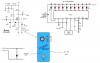
The only LED VU schematics I could find were for 10 LED's, and I assumed (perhaps wrongfully) that simply leaving the undesired LED's out would result in the desired effect, maintaining the viability of the circuit.
Please help me understand if this project is feasible, or if its value does not exceed its cost (both monetarily and time-wise). I have attached the schematics I would like to use and a visual guide for the plan. Thanks,
~Nate
I'm trying to adapt a circuit for a basic ~27 dB boost intended for use in a guitar pedal. I would like to build it, with these modifications: on/off LED (easy), and 5 LED VU meter, which reads the OUTPUT (post-boost effect) at a reasonable level (highest input volume from unamplified guitar signal reaching red LED at max boost). The VU meter would be a subjective measure (strictly serving the purpose of quick-glance notification of boost level) and will probably require an internal trim potentiometer for fine tuning.
The only LED VU schematics I could find were for 10 LED's, and I assumed (perhaps wrongfully) that simply leaving the undesired LED's out would result in the desired effect, maintaining the viability of the circuit.
Please help me understand if this project is feasible, or if its value does not exceed its cost (both monetarily and time-wise). I have attached the schematics I would like to use and a visual guide for the plan. Thanks,
~Nate