Hi everyone,
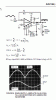
I was trying to design a full wave rectifier using the standard 4 diodes bridge circuit. But, my signal is attenuated by the diodes. I also have a signal offset after every half cycle like the picture below:
**broken link removed**
My full wave rectifier specifications are like follows:
1.Signal range: -5V to 5V.
2.Output range: 0V to 5V.
3.No offset or at least a very small one.
4.Accepts any input signal waveforms.
I don't think that using OP-Amps (Precise Full-Wave Rectifier) will resolve my problem because it contains only one input. The circuit need to accommodate any input signal waveforms where sometime the negative half cycle is not uniform.
Any question, design or idea is welcome.
Thank you
Stivfk
")