Continue to Site

Welcome to our site!

Electro Tech is an online community (with over 170,000 members) who enjoy talking about and building electronic circuits, projects and gadgets. To participate you need to register. Registration is free. Click here to register now.

  • Welcome to our site! Electro Tech is an online community (with over 170,000 members) who enjoy talking about and building electronic circuits, projects and gadgets. To participate you need to register. Registration is free. Click here to register now.

H bridge design

Status
Not open for further replies.

phoenox

New Member
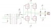
This h bridge circuit worked well for about a week, then one of the low side mosfets blew up. I am sure that these chips are capable of handling the motor current. I think that the problem may be caused by short duration shoot through when the input signal to the mosfets is switching from high to low. The voltage generally takes about 20 µs to switch. During this time there may be a short through the h bridge.

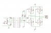
The signals from the left come from a microcontroller. They go to an optoisolator which controlls the mosfets.

I do not know how I can solve this problem?
 

Attachments

  • hbridge.jpg
    hbridge.jpg
    30.3 KB · Views: 371
Sorry about the poorly drawn schematic. I hope this is a little better.

The MOSFETS are FDS6681Z (P type) and FDS8812NZ (N type)
The datasheet says they should be good for 30 Volts, 20 Amps.
100 Amps pulsed.

I am actually only running them at 12 Volts despite what the first schematic said.

The optoisolator is LTV 847.
 

Attachments

  • hbridge.jpg
    hbridge.jpg
    22.4 KB · Views: 406
The design has multiple problems. First of all, you say it was working fine. I can't believe that. That bridge cannot be switched by a PIC. Your input voltage swing has to swing from zero to 12V to drive the bridge.
What is the purpose of T1?
What are the part numbers of your MOSFETs? When you post a schematic here, you need to include the values of all components.
What is your PIC supply voltage?
Let's deal with these first, then we'll get on to other issues.
 
Last edited:
The MOSFETS are FDS6681Z (P type) and FDS8812NZ (N type)
The datasheet says they should be good for 30 Volts, 20 Amps.

The optoisolator is LTV 847.

The PIC supply Voltage is 5V. The PIC drives the optoisolator. The optoisolator output does swing from 0 to 12V.

The transistor T1 is used as an inverter. Te microcontroller code was originally written to run a L298 but the L298 was not able to handle the motor current. I added the T1 transistor to save myself going through the code and changing every line of code from
motor_enable = 1; to motor_enable = 0; and vise versa. It also saves the microcontroller pin from having to sink the sum of the current sourced by both the other two lines(this would be at or above the maximum rating).

I have replaced the blown mosfet and the circuit is currently working, but I suspect that it will continue to destroy mosfets on a semiregular basis.
 
The PIC supply Voltage is 5V. The PIC drives the optoisolator. The optoisolator output does swing from 0 to 12V.
At the risk of sounding nasty: Why did you say the 300 ohm resistors were driven by the PIC?
You need to include the optoisolators in the schematic, with component values.
 
I'm guessing that the inputs come directly from the collectors of the optoisolators. If this is true, you need to do two things:
1. Replace the 300 ohm resistors with wire (zero ohms). The 300 ohm resistors will probably keep your N-channels from ever turning completely off.

2. Replace the 10k resistors with 47 ohms. The 10k's slow the switching times of the MOSFETs so much that you will get shoot-through current for a long time with each transition of the input. Changing them to 47Ω will not eliminate shoot-through, but it will help considerably.

What is the frequency of the input signals?
 
Here is another atempt at drawing an understandable schematic.

I have added an actual optoisolator symbol where I was using two rows of pins before. Also put the part numbers beside the mosfets and cleaned it up a little.

Hopefully now I will learn my lesson that the schematic is not something you just hack together so that you have airwires to route.

I apreciate your patience.
 

Attachments

  • hbridge.jpg
    hbridge.jpg
    39.3 KB · Views: 716
Here is another atempt at drawing an understandable schematic.

I have added an actual optoisolator symbol where I was using two rows of pins before. Also put the part numbers beside the mosfets and cleaned it up a little.

Hopefully now I will learn my lesson that the schematic is not something you just hack together so that you have airwires to route.

I apreciate your patience.
OK. If you read my previous post, ignore item 1 about removing the 300 ohm resistors. Just change out the 10k resistors.
What is the frequency of the input?
 
Last edited:
I have replaced the 10K resistors going to the mosfet gates with 47 Ohm resistors. I did not replace the resistors at T1. I don't think you meant for those to be replaced with 47 Ohm resistors.

The frequency is very slow. I just turn the motor on for 7-20 seconds every 15 minutes, then off again.
 
I have replaced the 10K resistors going to the mosfet gates with 47 Ohm resistors. I did not replace the resistors at T1. I don't think you meant for those to be replaced with 47 Ohm resistors.

The frequency is very slow. I just turn the motor on for 7-20 seconds every 15 minutes, then off again.
Apparently the direction is reversible (?).
 
I am using the mounting hardware from a big old satelite dish to move solar panels to face the sun.

The motor is actually a linear actuator with position feedback.

During the course of the day the actuator slowly lengthens to pivot the solar panels to face the sun. Then at midnight it has to reverse direction to come back to the starting point.

The mounting hardware for these old satelite dishes is almost exactly what is needed to follow the sun. I just had to build the electronic controller to make it work. Hopefully now it is completed.
 
Status
Not open for further replies.

Latest threads

New Articles From Microcontroller Tips

Back
Top