Hey there,
Well I have a cheapy black & decker KR504 500W hammer drill. Its virtually new and working fine but.. I wish to use it in a drill stand for half decent holes.
Its runout is shocking and its over powered, but right now its the only option I having for drilling aluminium for a project (cast aluminium, M4 bolt holes, 9mm depth).
Because like many hand drill the speed control is via the trigger switch, and the only way to keep it on hands free is via the hold switch (which holds the trigger fully on) it can only be used at full speed, which is LOUD and over kill - especially when countersinking aliminium.
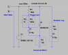
So, I decided to see if I could modify the trigger circuit to reduce the speed when the trigger is fully depressed (and held by the button). Saw a basic SCR circuit there, but I was surprised just how simple it is... SCR (600V 12A), a 150nF.. NO diode on the gate , a fix thick film printed resistor, and a variable resistor track. Along with a suppression cap across the circuit that is all.
Do you think if I replaced R1 (sets the minimum value of the trigger) with a 160k in series with a 1Meg pot, I could 'set' the maximum power? As this will be connected to live, despite the low current, I'll have it as a plastic housed preset pot inside deep inside the drill, with a hole to adjust it with a plastic screw driver. With the added pot at 0, it should behave the same (minimum 160k resistance), but when adjusted it should add more resistance (increasing phase shift of the power waveform) and in effect simulate releasing the trigger a bit slowing it down.
Is it this simple? or am I missing something... I attached a schematic, values are measured - except the SCR which is MCR12DSM. The resistors are all printed thick film, but the resistor in parallel with the carbon track... is an odd shape (makes a difference?).
If anyone can chime in, I'd be grateful") I'm afraid I'm not overly well versed in SCR circuits (aside form basic triggers).
I'm afraid I'm not overly well versed in SCR circuits (aside form basic triggers).
Well I have a cheapy black & decker KR504 500W hammer drill. Its virtually new and working fine but.. I wish to use it in a drill stand for half decent holes.
Its runout is shocking and its over powered, but right now its the only option I having for drilling aluminium for a project (cast aluminium, M4 bolt holes, 9mm depth).
Because like many hand drill the speed control is via the trigger switch, and the only way to keep it on hands free is via the hold switch (which holds the trigger fully on) it can only be used at full speed, which is LOUD and over kill - especially when countersinking aliminium.
So, I decided to see if I could modify the trigger circuit to reduce the speed when the trigger is fully depressed (and held by the button). Saw a basic SCR circuit there, but I was surprised just how simple it is... SCR (600V 12A), a 150nF.. NO diode on the gate , a fix thick film printed resistor, and a variable resistor track. Along with a suppression cap across the circuit that is all.
Do you think if I replaced R1 (sets the minimum value of the trigger) with a 160k in series with a 1Meg pot, I could 'set' the maximum power? As this will be connected to live, despite the low current, I'll have it as a plastic housed preset pot inside deep inside the drill, with a hole to adjust it with a plastic screw driver. With the added pot at 0, it should behave the same (minimum 160k resistance), but when adjusted it should add more resistance (increasing phase shift of the power waveform) and in effect simulate releasing the trigger a bit slowing it down.
Is it this simple? or am I missing something... I attached a schematic, values are measured - except the SCR which is MCR12DSM. The resistors are all printed thick film, but the resistor in parallel with the carbon track... is an odd shape (makes a difference?).
If anyone can chime in, I'd be grateful
I'm afraid I'm not overly well versed in SCR circuits (aside form basic triggers).