Continue to Site

Welcome to our site!

Electro Tech is an online community (with over 170,000 members) who enjoy talking about and building electronic circuits, projects and gadgets. To participate you need to register. Registration is free. Click here to register now.

  • Welcome to our site! Electro Tech is an online community (with over 170,000 members) who enjoy talking about and building electronic circuits, projects and gadgets. To participate you need to register. Registration is free. Click here to register now.

Harley Davidson Fuel Gauge

caboguy

New Member
Hi everyone. I'm brand new to this forum and I thank you all for taking the time to read and possibly reply to my thread.
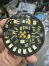
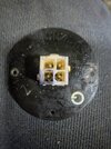
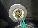
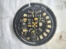
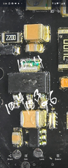
I have a fuel gauge that goes on a Harley Davidson Softail. It has three wires power, ground, and one that goes to the sending unit that measures the fuel level in ohms. All was going well until I reversed the polarity on the wires, now it doesn't power up. I'm trying to locate the component on the circuit board that I blew and replace it with a part from another board from a device that I'm not using.
Brand new to electronics at the circuit board level but I follow instructions meticulously.
I'm also looking to create my own programmable ignition control unit for the motorcycle with Bluetooth functionality (the current aftermarket units available do not have wireless functionality) but that's probably a other thread.
Where do I begin in locating the problem on the fuel gauge? Is there a part that is most likely the culprit? Anything else I should know or do?
Thanks in advance for your help and patience with a newbie!
 
Hi Zapper,
Wires to the gauge. The sender has a slider which has more or less resistance as it goes up or down. No power goes to it. Attached are pics of the board I'm dealing with:
 

Attachments

  • IMG_20240923_235709926_HDR_AE.jpg
    IMG_20240923_235709926_HDR_AE.jpg
    6.1 MB · Views: 44
  • IMG_20240923_235829519_HDR_AE.jpg
    IMG_20240923_235829519_HDR_AE.jpg
    6.2 MB · Views: 43
  • IMG_20240923_232411846_AE.jpg
    IMG_20240923_232411846_AE.jpg
    6.4 MB · Views: 44
Excellent pic. Maybe someone else can take a look at this but I see
no obvious part damage. Per chance is there an inline fuse in the power
lead to this board ?

If you can get a schematic for the board that would aid in doing some
short checks.
 
It's fused at the fuse box under the seat of the motorcycle. There's actually only three fuses so the gauge shares a fuse with the instrument panel. If it was a fuse, I would have known immediately.
I doubt Harley Davidson will give me a schematic and trying to get ahold of the person or people who have access to it seems like an impossible task.
I'm hoping I can find the faulty part with a multimeter if I knew how to go about it. Finding a replacement and soldering it on the board will it be a problem as it looks relatively simple.
 
Any Harley forums out their you can work with trying to get schematic ?

Without it debugging/finding bad stuff with just ohmmeter trial by fire....

If there are tantalums on board usually reverse polarity will blow them.

ICs with reverse polarity usually blow internal bond wires to IC pads, the die
in the package, so you would read open on power pin, maybe.....
 
Actually, don't see how reversing the wires from the sender would cause damage.
I would think it would just reverse the gauge output (i.e. empty tank would give a tank full reading).
 
I didn't reverse the wires from the sender, I reversed the positive and negative wires from the battery.
You talked about the sender wires, so I assumed that was what was reversed.
This is first you mentioned reversal of the battery voltage which is an entirely different, (and more smelly), kettle of fish.

Don't see how to determine what failed without a schematic of the board.
 
Can you read any part numbers off the large IC's ?

Tilt board in strong light, use a magnifying glass, a longshot but might
be readable. I have used photo software, and edge detection, that
sometimes works to reveal text..
 
I didn't reverse the wires from the sender, I reversed the positive and negative wires from the battery.

In which case you will have fried something - there's an obvious voltage regulator at the left of the picture (the device with the tab at the top), connect the unit to power (the right way round) and measure the voltages on the three lower pins, you should have 12V, 0V (ground) and probably 5V. Post the results here.

If they are OK, then you've most likely fried one of the two large IC's, one is probably a micro-controller?, and the other perhaps an LED driver?. The micro will be irreplaceable, as you wouldn't be able to get the firmware for it, the other 'might' be replaceable if you can find a number on it.

Bear in mind, auto electronics often use obscure parts, or in-house numbers, which means they are difficult or impossible to source.

If the voltages on the regulator are missing, then you might have more of a chance.
 
an obvious voltage regulator at the left of the picture (the device with the tab at the top), connect the unit to power (the right way round) and measure the voltages on the three lower pins, you should have 12V, 0V (ground) and probably 5V. Post the results here.

Hi Nigel,
10.4 on the large tab, 10.4, 10.3, 9.6 on the three below. Negative of multimeter connected to battery. Battery reads 12.66 at terminals.
Tried every angle under multiple lights. No visible numbers.
 

Attachments

  • Screenshot_20240926-175438_Photos.png
    Screenshot_20240926-175438_Photos.png
    2.9 MB · Views: 1
Can you read any part numbers off the large IC's ?

Tilt board in strong light, use a magnifying glass, a longshot but might
be readable. I have used photo software, and edge detection, that
sometimes works to reveal text..
Hi Danadak,
Tried everything. It's almost as if they are polished. Maybe on the bottom?
 

Latest threads

New Articles From Microcontroller Tips

Back
Top