Continue to Site

Welcome to our site!

Electro Tech is an online community (with over 170,000 members) who enjoy talking about and building electronic circuits, projects and gadgets. To participate you need to register. Registration is free. Click here to register now.

  • Welcome to our site! Electro Tech is an online community (with over 170,000 members) who enjoy talking about and building electronic circuits, projects and gadgets. To participate you need to register. Registration is free. Click here to register now.

HCF4017BE problem

Status
Not open for further replies.

unlist

New Member
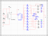
Can any1 help me with this IC . I'm trying to make a traffic light using IC 555 and 4017 .
I use multisim to create a design like the file i attached .
There not much problem when i run it in multisim .
Then I bought 2 IC : NE555P and HCF4017BE.
A problem is that when i do everything like in design, only 4th and 12th leg of IC 4017 light up my led . But it light up just like if i connect my led directly to the output of IC 555 . It feel like my 4017 IC only connect between leg 4, 12 and 14 and that all .
So any1 know what the problem here ?
Thank for your help and sorry because im bad at english .
 

Attachments

  • ?GT.png
    ?GT.png
    45.6 KB · Views: 4,387
dont know why . seem like it work now . if there a problem i will really need your help :D thank very much
 
Last edited:
The 4017 will source only enough current to make the LEDs quite dim. You will likely need a transistor to switch the LEDs...
 
you are welcome, also read the bellow thread until the end. its for 4 street system.
https://www.electro-tech-online.com/threads/traffic-light-help-sos.99450/
I done everything with my design but still, thank for the link

The 4017 will source only enough current to make the LEDs quite dim. You will likely need a transistor to switch the LEDs...
I use 9V input and put a 680Ω before each Led, they work well, not dim at all . But thank for advise .
 
If you have a low impedance clock driving a CMOS circuit, the circuit may operate even with no power applied since the V+ will charge up through the protection diode between the input and the Vdd line. This diode acts like a rectifier to provide power to the circuit from the clock. But that's not a desired way to operate the circuit.
 
Status
Not open for further replies.

Latest threads

New Articles From Microcontroller Tips

Back
Top