Hello everyone,
I am new to this forum and also to the topic of microcontrollers. I am working on a project for a course, but since I don't have much experience, I feel a bit lost.
The project is as follows:
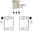
This assembler code for a PIC16F84A microcontroller consists of a system with two tanks, each with two level sensors (high level and low level) (switches in the case of the simulation, which are set in pull-up). When the switch is open (1), it means that the water is above that level, and when it is closed (0), it means that it is below the level.
The pump will turn off whenever the high-level switch is open (1). Also, if the high-level switch opens (1) and the low-level switch is closed (0), the pump will stop and a LED will light up indicating an error (since this would mean that the low-level sensor is indicating that the water is below that level, but the high-level sensor is indicating that the tank is full). It is important to note that if the low-level switch is open (1) and the high-level switch is closed (0), the pump will not turn off, indicating that the tank has not yet filled.
The same behavior occurs for the second tank, independently of the first one.
Additionally, the project has a blinking LED that oscillates every second, using the TMR0.
This project uses interrupts for the switches and for the oscillation of the blinking LED with TMR0.
In tank 1: the high level is at RB4, the low level at RB5, the error LED at RB1, and the pump at RA0.
In tank 2: the high level is at RB6, the low level at RB7, the error LED at RB2, and the pump at RA1.
The blinking LED is at RB3.
The code is as follows:
The issue in this code is that the pump for tank 1 does not turn on at any moment. Additionally, the switches in this tank are functioning as established, but they are operating on the pump for tank 2.
Regarding the frequent LED and the two error LEDs, they are working correctly as specified in the statement. In the same way, the two level switches for tank 2 operate correctly on their respective pump.
If you can help me resolve the issue, I would greatly appreciate it.
I am new to this forum and also to the topic of microcontrollers. I am working on a project for a course, but since I don't have much experience, I feel a bit lost.
The project is as follows:
This assembler code for a PIC16F84A microcontroller consists of a system with two tanks, each with two level sensors (high level and low level) (switches in the case of the simulation, which are set in pull-up). When the switch is open (1), it means that the water is above that level, and when it is closed (0), it means that it is below the level.
The pump will turn off whenever the high-level switch is open (1). Also, if the high-level switch opens (1) and the low-level switch is closed (0), the pump will stop and a LED will light up indicating an error (since this would mean that the low-level sensor is indicating that the water is below that level, but the high-level sensor is indicating that the tank is full). It is important to note that if the low-level switch is open (1) and the high-level switch is closed (0), the pump will not turn off, indicating that the tank has not yet filled.
The same behavior occurs for the second tank, independently of the first one.
Additionally, the project has a blinking LED that oscillates every second, using the TMR0.
This project uses interrupts for the switches and for the oscillation of the blinking LED with TMR0.
In tank 1: the high level is at RB4, the low level at RB5, the error LED at RB1, and the pump at RA0.
In tank 2: the high level is at RB6, the low level at RB7, the error LED at RB2, and the pump at RA1.
The blinking LED is at RB3.
The code is as follows:
Code:
#include "p16f84a.inc" ; Include definition file for PIC16F84A
; CONFIG __CONFIG _FOSC_HS & _WDTE_OFF & _PWRTE_ON & _CP_OFF

; Definition of variables in the RAM area
cblock 0x0c
    iterate_1s ; Variable to count iterations of 1 second
endc

; Program start address configuration
org 0
    goto START       ; Jump to the start of the main program

; Interrupt vector (position 4)
org 4
    goto INTERRUPTS  ; Jump to the interrupt routine

;-----------------------------------------------------------
; Interrupt Routine
;-----------------------------------------------------------
INTERRUPTS
    btfss INTCON, T0IF ; Check if the interrupt was caused by Timer0 overflow
    goto $+2           ; If not caused by Timer0, jump to the next instruction
    goto LED_BLINK_FREQUENT    ; If caused by Timer0, jump to the LED blink routine

    ; Check if an external interrupt occurred on PORTB
    BTFSS INTCON, 0    ; If the external interrupt flag (RBIF, bit 0) is NOT active, return immediately from the interrupt.
    RETFIE             ; Return from the interrupt without doing anything.

    ; Check the state of the high-level sensor (RB4)
    BTFSS PORTB, 4     ; If RB4 is 0 (switch closed), return (normal condition), i.e., ignore the interrupt.
    goto $+2           ; Return from the interrupt without modifying the operation.

    ; If we reach here, RB4 is 1 (high-level switch open) and the pump must be turned off.
    CALL TURN_OFF_PUMP_1 ; Jump to the routine that turns off the pump and evaluates the error.

    BTFSS PORTB, 6     ; If RB6 is 0 (switch closed), return (normal condition), i.e., ignore the interrupt.
    goto START        ; Return from the interrupt without modifying the operation.

    ; If we reach here, RB6 is 1 (high-level switch open) and the pump must be turned off.
    Call TURN_OFF_PUMP_2 ; Call the routine to turn off the second pump.

;-----------------------------------------------------------
; Main Program (START)
;-----------------------------------------------------------
START
    ; Switch to bank 1 to configure TRISA and TRISB
    bsf STATUS, 5      ; Select bank 1

    ; Port A configuration:
    ; RA0 and RA1 will be outputs (e.g., RA0 for the pump)
    ; RA2 to RA4 will be inputs (not used in this example)
    movlw b'11100'     ; Configuration: bits 4-2 as 1 (inputs) and bits 1-0 as 0 (outputs)
    movwf TRISA        ; Set the direction of port A

    ; Port B configuration:
    ; RB0: input, RB1 to RB3: outputs (e.g., RB1 for error LED)
    ; RB4 to RB7: inputs (sensors: RB4 high level, RB5 low level, RB6 and RB7 unused)
    movlw b'11110001'  ; Direction configuration for port B
    movwf TRISB        ; Set the direction of port B

    ; Timer0 configuration with prescaler assigned
    movlw b'00000111'  ; PSA=0 (prescaler assigned to Timer0) and PS2:PS0 = 111
    movwf OPTION_REG   ; Configure OPTION_REG

    ; Return to bank 0 to configure interrupts
    bcf STATUS, 5      ; Select bank 0

;-----------------------------------------------------------
; Configure TMR0
;-----------------------------------------------------------

    movlw .223         ; Load TMR0 with the value needed for 8ms
    movwf TMR0

    movlw .122         ; Load the number of iterations to reach 1 second
    movwf iterate_1s

    clrf PORTA         ; Clear the ports
    clrf PORTB

    ; Enable global interrupts, external interrupt, and PORTB interrupt
    movlw b'10111000'  ; GIE=1, TMR0IE=1, INTE=1, and RBIE=1
    movwf INTCON       ; Configure the corresponding bits

;-----------------------------------------------------------
; Sensor Code
;-----------------------------------------------------------

    ; Normal pump evaluation:
    ; Check the high-level sensor (RB4) in the main routine.
    BTFSC PORTB, 4     ; If RB4 is 0 (switch closed), skip the next jump.
                       ; This indicates that the water has not reached the high level.
    GOTO DISCARD_ERROR_1 ; If RB4 is 1, jump to the error discard part.

    ; If the high-level sensor is closed (0), turn on the pump.
    BSF PORTA, 0       ; Turn on the pump (RA0 = 1)

    BTFSC PORTB, 6     ; If RB6 is 0 (switch closed), skip the next jump.
                       ; This indicates that the water has not reached the high level.
    GOTO DISCARD_ERROR_2 ; If RB6 is 1, jump to the error discard part.

    ; If the high-level sensor is closed (0), turn on the pump.
    BSF PORTA, 1       ; Turn on the pump (RA1 = 1)

;-----------------------------------------------------------
; INFINITE LOOP WAITING FOR INTERRUPTS
;-----------------------------------------------------------
LOOP
    goto LOOP          ; Infinite loop to maintain execution

;-----------------------------------------------------------
; Routine to Discard Error
;-----------------------------------------------------------
DISCARD_ERROR_1
    ; Evaluate the low-level sensor (RB5)
    BTFSS PORTB, 5     ; If RB5 is 1 (switch open), discard the error.
                       ; If it is 0, an error condition occurs.
    CALL ERROR_1       ; Call the error routine (turn on error LED) if RB5 is 0.

    RETFIE             ; Return from the interrupt

;-----------------------------------------------------------
; Error Routine
;-----------------------------------------------------------
ERROR_1
    ; When an error occurs (RB4=1 and RB5=0):
    ; Turn off the pump and turn on the error LED.
    BCF PORTA, 0       ; Turn off the pump (RA0 = 0)
    BSF PORTB, 1       ; Turn on the error LED (RB1 = 1)
    RETURN             ; Return to the routine that called ERROR_1

;-----------------------------------------------------------
; Routine to Discard Error
;-----------------------------------------------------------
DISCARD_ERROR_2
    ; Evaluate the low-level sensor (RB7)
    BTFSS PORTB, 7     ; If RB7 is 1 (switch open), discard the error.
                       ; If it is 0, an error condition occurs.
    CALL ERROR_2       ; Call the error routine (turn on error LED) if RB7 is 0.

    RETFIE             ; Return from the interrupt

;-----------------------------------------------------------
; Error Routine
;-----------------------------------------------------------
ERROR_2
    ; When an error occurs (RB6=1 and RB7=0):
    ; Turn off the pump and turn on the error LED.
    BCF PORTA, 1       ; Turn off the pump (RA1 = 0)
    BSF PORTB, 2       ; Turn on the error LED (RB2 = 1)
    RETURN             ; Return to the routine that called ERROR_2

;-----------------------------------------------------------
; Routine to Turn Off the Pump
;-----------------------------------------------------------
TURN_OFF_PUMP_1
    ; Turn off the pump immediately
    BCF PORTA, 0       ; Turn off the pump (RA0 = 0)
    ; Then jump to the routine to evaluate or discard the error (if required)
    GOTO DISCARD_ERROR_1

TURN_OFF_PUMP_2
    ; Turn off the pump immediately
    BCF PORTA, 1       ; Turn off the pump (RA1 = 0)
    ; Then jump to the routine to evaluate or discard the error (if required)
    GOTO DISCARD_ERROR_2

;-----------------------------------------------------------
; Frequent LED Blink Routine
;-----------------------------------------------------------
LED_BLINK_FREQUENT
    movlw .223         ; Load TMR0 with the value needed for 8ms
    movwf TMR0
    ; Load the number of iterations to reach 1 second
    decfsz iterate_1s,f ; Decrement iterate_1s and save it in itself
    goto end_ISR       ; Not 0, go to end_ISR to clear TMR0 flag
    btfsc PORTB,3      ; Is 0, check the state of the 1Hz LED
    goto ON_led        ; If it is on (1), go to ON to turn it off
    goto OFF_led       ; If it is off (0), go to OFF to turn it on

OFF_led
    bsf PORTB,3        ; Turn on the LED
    movlw .122         ; Load iterate_1s
    goto times         ; Load into iterate_1s

ON_led
    bcf PORTB,3        ; Turn off the LED
    movlw .122         ; Load iterate_1s
    goto times         ; Load into iterate_1s

times
    movwf iterate_1s

end_ISR
    bcf INTCON, T0IF   ; Clear TMR0 flag
    retfie             ; Return from the interrupt

end
The issue in this code is that the pump for tank 1 does not turn on at any moment. Additionally, the switches in this tank are functioning as established, but they are operating on the pump for tank 2.
Regarding the frequent LED and the two error LEDs, they are working correctly as specified in the statement. In the same way, the two level switches for tank 2 operate correctly on their respective pump.
If you can help me resolve the issue, I would greatly appreciate it.