Continue to Site

Welcome to our site!

Electro Tech is an online community (with over 170,000 members) who enjoy talking about and building electronic circuits, projects and gadgets. To participate you need to register. Registration is free. Click here to register now.

  • Welcome to our site! Electro Tech is an online community (with over 170,000 members) who enjoy talking about and building electronic circuits, projects and gadgets. To participate you need to register. Registration is free. Click here to register now.

help me to understand this

Status
Not open for further replies.

imgemini

New Member
hi friend

this criciut is for sine wave genrator using the IC called NC-1458 which have 8 pin's but criciut seing 4 is he using one IC ?.... after design from where we know it,s genrating sine ware
 

Attachments

  • square_wave_circuit.jpg
    square_wave_circuit.jpg
    34.5 KB · Views: 778
The MC1458 is a dual op-amp. Pin assignments are as follows:

Pin 1 - Output A
Pin 2 - Inverting Input A
Pin 3 - Non-inverting Input A
Pin 4 - V(ee)
Pin 5 - Non-inverting Input B
Pin 6 - Inverting Input B
Pin 7 - Output B
Pin 8 - V(cc)
 
The chip has two op-amps so he is using only one chip thats how schematics are drawn. So yes only one chip is used.
 
thx,s but

hi friend
can u plz help me to understand from where i can get output sine wave . any way i can know in which frequency it is working on


:!:
 
You will get a square wave from pin 1 and a sawtooth from pin 7.
The frequency will be roughly between 100 and 1kHz. No sine wave.
:?
 
hi

what is meaning by 10 a 12 a here in cricuit plz
 

Attachments

  • square_wave_circuit_159.jpg
    square_wave_circuit_159.jpg
    2.9 KB · Views: 630
Re: hi

imgemini said:
what is meaning by 10 a 12 a here in cricuit plz


Well, obviously they are the same node and it is very poor practice to give the same node more than one name, so I might assume that really there is a physical connection point there like a connector or some other means or physical connect-disconnect. If this is the case, it is also poorly drawn because they are not drawn properly..
 
hi

hi
this ad-resistor the GND and the out both are connected together . :confused:
 

Attachments

  • square_wave_circuit_204.jpg
    square_wave_circuit_204.jpg
    2.6 KB · Views: 544
Re: hi

imgemini said:
hi
this ad-resistor the GND and the out both are connected together . :confused:

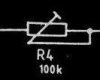
It's simply wired as an adjustable resistor, giving just two connections. When they are wired using three connections (like a volume control) it's called a potentiometer.
 
hi

plesae tell me what is the name of this part


is this Varactor diod or swtch diod ...or what .and plesae see the circuit above bcoz making any statement :arrow:
 
as picture shows


10a & 12a closed ... 10c & 14c opened ----> square wave

10a & 12a closed ... 10c & 14c closed ----> sawtooth
 
Status
Not open for further replies.

Latest threads

New Articles From Microcontroller Tips

Back
Top