Electro Tech is an online community (with over 170,000 members) who enjoy talking about and building electronic circuits, projects and gadgets. To participate you need to register. Registration is free. Click here to register now.
Welcome to our site! Electro Tech is an online community (with over 170,000 members) who enjoy talking about and building electronic circuits, projects and gadgets. To participate you need to register. Registration is free. Click here to register now.
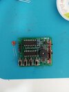
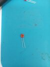
I'd like to solder the ceramic capacitor for decoupling across GND and VCC of U1/U3. I don't know what the best placement would be on this circuit, so help with visual markings on the photo would be helpful!
Attachments
2024-08-27-15-24-31-400.jpg
2.4 MB
· Views: 11
2024-08-27-15-24-09-762.jpg
2.2 MB
· Views: 11
Screenshot 2024-07-27 at 08-02-25 Pro Zestaw do nauki lutowania 4 x układy DIY KIT - Sklep Opi...png
Solder them between pins 7 (GND) & 14 (VCC) on the two DIP (Dual Inline Packages) on the solder side of the board. Make sure the leads do not touch any other pins or traces.
The best placement is to have the shortest total length of ground and Vcc leads, so that is the length of ground lead inside the IC (which you can't do anything about), the ground track from pin 7 to where you solder the capacitor, the ground side capacitor lead, the Vcc side capacitor lead, the Vcc track from where you solder the capacitor to pin 14 and finally the Vcc lead inside the IC (which you can't do anything about).
I can't see the layout of ground and Vcc tracks and if all the tracks take long paths, you might be best to solder the capacitors above the ICs, or directly under them as Papabravo suggests.
As an aside, to show the importance of short wire lengths, in the 1980s, Texas Instruments came out with a logic series, the 74AC11000 series, that had 2 or more ground pins, and two or more Vcc pins, in the middle of the sides of the IC, to minimise the length of the wires to the decoupling capacitors. https://www.ti.com/lit/ds/symlink/74ac11000.pdf
This site uses cookies to help personalise content, tailor your experience and to keep you logged in if you register.
By continuing to use this site, you are consenting to our use of cookies.