Electro Tech is an online community (with over 170,000 members) who enjoy talking about and building electronic circuits, projects and gadgets. To participate you need to register. Registration is free. Click here to register now.
Welcome to our site! Electro Tech is an online community (with over 170,000 members) who enjoy talking about and building electronic circuits, projects and gadgets. To participate you need to register. Registration is free. Click here to register now.
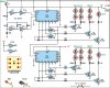
Hi Guys I'm a newbie to electronics. Need help with connections on IC1 in the attached schematic.Not sure which pins hook together and which ones don't.
I don't know what the open circle means on pin 6,9,2,4,10 and 12
While drawing the circuit diagrams (schematics), there are conventions. Whenever a wire symbol crosses another wire,, as per old practice, a bow (what you called open circle)is made and then the line continues. where ever there is a connection at the crossing or T- joint , it is indicated by a darkened spot across it.
As per modern practice, a simple crossing of wires indicated is NO cross connection( I meant no open circle). If dark spot is there, it is a cross connection. At places of T connection, even if the spot is not there , it is connection.
Hope this serves to have a start of how to study a circuit schematic.
Thanks Mike.
Many times I get fundamental doubts even after having worked on technical side of Telecom, I try to read preliminary books, I really enjoy them and correct my misconceptions.
I think you're talking about the inversion sign on the output of the schmidt triggers (IC1a-f).
An inversion circle simply means that the original incoming signal is inverted on the output, i.e, if its a logic high in, a logic low will be the result after inversion.
The triangle with open circle on the output is the standard schematic symbol for a logic inverter.
OOPS. I bungled the issue.
Hai AllVol, you got him correct. The OP was talking about the Invertion symbol at th the outputs of the NOT gates .
Thanks Allvol.
I got the circuit to work finally.The data sheet for the 40106 shows pin 9 and 8 are backward in the circuit schematic. I switched them and the circuit worked find. Thanks for your help. OldCoalMiner
This site uses cookies to help personalise content, tailor your experience and to keep you logged in if you register.
By continuing to use this site, you are consenting to our use of cookies.

")