prof328
Member
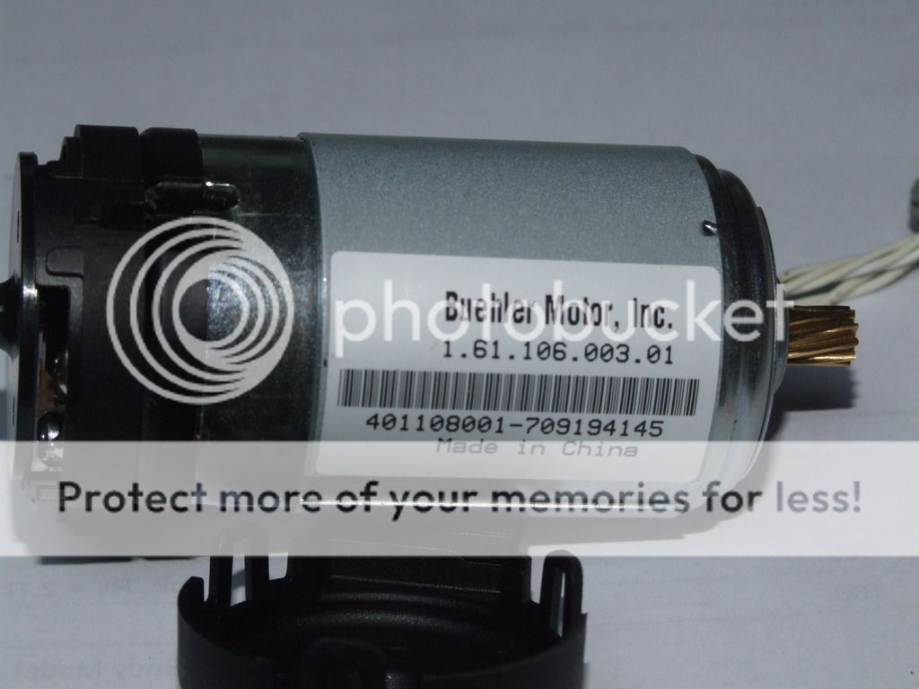
I recently retired a Xerox phaser 8560 solid ink printer, and rather than just throwing it away decided to dismantle it to see what bits I might be able to use in future projects.
Two electric motors intrigued me as they had photo reflective encoders built in, however I could find very little information on them.
I have found what looks like the reflective optical encoder with the following data sheet, but can not be certain.
https://cdn.usdigital.com/assets/general/168_aedr_datasheet.pdf
I also now have an iso-tech isr 650 analogue oscilloscope, although feel a bit intimidated by it, and try as I may I can not get the two out of phase square waves to show on the scope. The high state is 2.4V and the low state is 0.4V.
I can not see the underside of the circuit board, and have been unsuccessful in working out what the pin connections are.
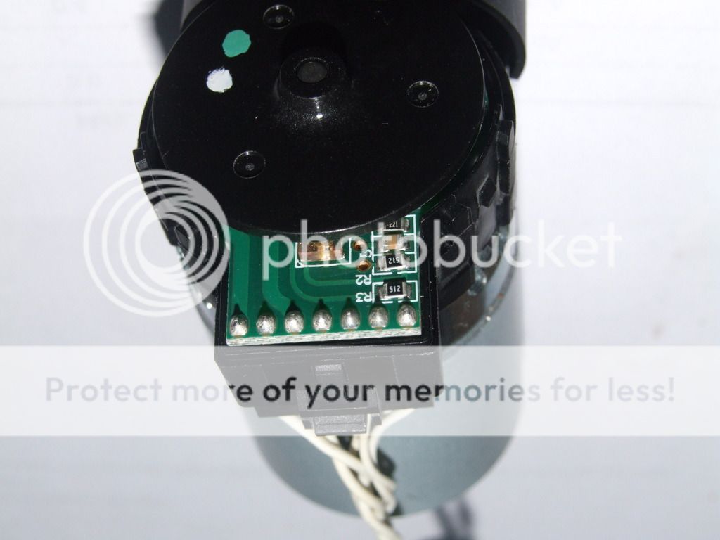
There are seven connections and six wires, the second connection from the left is unused.
From the left, the end one and the third are connected to the motor, if I connect with 4.5V the motor runs.
The last four are connected to the encoder, and if the data sheet is in fact for this encoder the following pins seem to make sense.
4 GND 3 LED
5 CH A 2 GND
6 VCC 1 CH B
The rightmost wire has a trace connecting all of the four components.
The data sheet recommends a 220 ohm resistor between pins 6 and 3 and it looks like there is one, the top most resistor is R1 a 220 ohms, the trace running under the text R2 connects it to pin 6.
The second component from the top is a capacitor and connected to pin 2
The third from the top is R2 a 5.1k resistor and connected to pin 1
The bottom one is R3 a 5.1k resistor connected to pin 5 and also to the fourth wire from the right.
I am assuming that the right most wire is Vcc,
Can some one point me in the right direction in order to see the outputs of channel A and B ?
Two electric motors intrigued me as they had photo reflective encoders built in, however I could find very little information on them.
I have found what looks like the reflective optical encoder with the following data sheet, but can not be certain.
https://cdn.usdigital.com/assets/general/168_aedr_datasheet.pdf
I also now have an iso-tech isr 650 analogue oscilloscope, although feel a bit intimidated by it, and try as I may I can not get the two out of phase square waves to show on the scope. The high state is 2.4V and the low state is 0.4V.
I can not see the underside of the circuit board, and have been unsuccessful in working out what the pin connections are.
There are seven connections and six wires, the second connection from the left is unused.
From the left, the end one and the third are connected to the motor, if I connect with 4.5V the motor runs.
The last four are connected to the encoder, and if the data sheet is in fact for this encoder the following pins seem to make sense.
4 GND 3 LED
5 CH A 2 GND
6 VCC 1 CH B
The rightmost wire has a trace connecting all of the four components.
The data sheet recommends a 220 ohm resistor between pins 6 and 3 and it looks like there is one, the top most resistor is R1 a 220 ohms, the trace running under the text R2 connects it to pin 6.
The second component from the top is a capacitor and connected to pin 2
The third from the top is R2 a 5.1k resistor and connected to pin 1
The bottom one is R3 a 5.1k resistor connected to pin 5 and also to the fourth wire from the right.
I am assuming that the right most wire is Vcc,
Can some one point me in the right direction in order to see the outputs of channel A and B ?
