Continue to Site

Welcome to our site!

Electro Tech is an online community (with over 170,000 members) who enjoy talking about and building electronic circuits, projects and gadgets. To participate you need to register. Registration is free. Click here to register now.

  • Welcome to our site! Electro Tech is an online community (with over 170,000 members) who enjoy talking about and building electronic circuits, projects and gadgets. To participate you need to register. Registration is free. Click here to register now.

Help w/hv9910 LED switcher

Status
Not open for further replies.

technogeek

New Member
Hi guys,

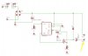
As you probably remember, I'm trying to build a mains powered switcher power supply... Well, I got it to work... sorta.

I made the values for the components for a 60V @0.7A LED bank... Now these should work for a 16V @o.7A bank, right? Here's what happens...

Powers on, and there's a high pitched whine. 100khz shouldn't be heard!! Anyways, the LED's light, which is a good sign. I check the current through them, and it shows 0.3A. :confused: :confused:

WORSE, when I touch the "negative" lead (the one coming off the inductor), the LED's brighten and the current rises to 0.4A. Meanwhile the pitch of the hum changes in frequency...

What did i do wrong? This can't be normal! Granted, the inductor is larger than it should be for just 6 LEDs, but I didn't think that would be a problem? And what's with the touch sensitivity!?!

In need of some switcher expertise..........................:eek:
 
Since you are still with us, let's see a schematic of your circuit with an arrow to the point that you are touching. :D
 
What do you mean "still with us"? Did you expect me to electrocute myself, or "get my answer and run"? ;)

Attached is the schematic... Ignore L1 looking like a cap... C1 is 68uF and R2 is 0.324 ohms... the funny X things are my fuse holder pads

Also, if I just touch the insulation and it does the same thing.
 

Attachments

  • switcher.jpg
    switcher.jpg
    50 KB · Views: 877
Well, for starters you need a capacitor across the load (Between the two Xs pointed by the yellow arrow). The ripple on the LEDs would be huge without it and this explains the low average current you are measuring.
Ignore L1 looking like a cap
Search for "inductor" in eagle or "L-USL3*" to get the proper symbol for your coil when using the ADD part command.
 
What do you mean "still with us"?
Or shock and run! :eek:

Not according to the app note I have here
I see.... I guess that is the more cost effective way of doing it. But without a cap, you won't be able to measure the LED current with a normal volt/amp meter. You'll need a resistor in series with the LED anode and a scope with a floating gnd on the probe; the "gnd" of the probe would have to goto the DC input side of the switcher (C1+) to avoid upsetting your switcher, so be carefull!
I suspect that the reason why your circuit behaves strangely, when you touch it in that special spot, is because of the high voltage & frequency at that point is being coupled into the air and into your circuit via your body. I wonder what your niebours TV looks like when you do this. :D
As for it oscillating at a lower frequency, make sure that the supply (pins 6&7) are properly bypassed to ground with a cap with a low esr. It is also possible that you are hearing the 120Hz rectified line voltage ripple modulating the 100Khz switching frequency....
 
Powers on, and there's a high pitched whine. 100khz shouldn't be heard!!
A quote from the data sheet:
However, the designer must
keep in mind that the input voltage must be maintained higher
than 2 times the forward voltage drop across the LEDs. This
limitation is related to the output current instability that may
develop when the HV9910 buck converter operates at a
duty cycle greater than 0.5. This instability reveals itself as
an oscillation of the output current at a sub-harmonic of the
switching frequency.
 
kchriste said:
As for it oscillating at a lower frequency, make sure that the supply (pins 6&7) are properly bypassed to ground with a cap with a low esr. It is also possible that you are hearing the 120Hz rectified line voltage ripple modulating the 100Khz switching frequency....

DOH!

I forgot it! I had it spec'd out, but forgot to order the part and put it on the board! Thanks for the reminder! (big time!)

However, the designer must
keep in mind that the input voltage must be maintained higher
than 2 times the forward voltage drop across the LEDs. This
limitation is related to the output current instability that may
develop when the HV9910 buck converter operates at a
duty cycle greater than 0.5. This instability reveals itself as
an oscillation of the output current at a sub-harmonic of the
switching frequency.

Vin is definately >2*Vout

I think you probably hit the nail on the head with the small low esr cap though.

I guess my #1 question now though, is why is it not putting the full 0.7A into my LED's? The cap can't possibly be the reason?
 
Last edited:
Damn. I wrote an answer and I guess I hit the wrong button and it's not here.

That design will fail to operate on a fixed freq when the inductor is large for the freq. You MUST use an RC network with a time constant of over 300nS (but not too much over) on the current sense wire. Otherwise, say you have a large inductor for low ripple and insensitivity to input voltage. You shoot for 1 amp current. The inductor only decays to 990mA at the end of the cycle. The 9910 turns on the gate, say the gate charges with a brief 50mA current pulse- that goes through the gate and the current sense resistor. 9910 senses 1040mA and shuts off instantly, skipping the cycle. Happens next cycle too, even though the inductor's decayed to 980mA. Like 6 cycles later the inductor's at 940mA, gate charge makes a brief 990mA reading, not enough to trip the 9910, so the 9910 gets past that pulse then has a nice long charging cycle for once to put the inductor current back up to 1 amp. Effectively it may be operating at a fraction of the intended freq due to cycle-skipping.

The 9910 has a fixed on-time configuration if the Vout/Vin is more than 0.5 which will be stable.

The output does NOT need a cap.

Isn't that inductor huge for what you want to do? Are you even sure it's not saturating? Larger inductors usually come with lower saturation current and higher resistance unless you go with a physically larger device.
 
Last edited:
Oznog said:
Damn. I wrote an answer and I guess I hit the wrong button and it's not here.

That design will fail to operate on a fixed freq when the inductor is large for the freq. You MUST use an RC network with a time constant of over 300nS (but not too much over) on the current sense wire. Otherwise, say you have a large inductor for low ripple and insensitivity to input voltage. You shoot for 1 amp current. The inductor only decays to 990mA at the end of the cycle. The 9910 turns on the gate, say the gate charges with a brief 50mA current pulse- that goes through the gate and the current sense resistor. 9910 senses 1040mA and shuts off instantly, skipping the cycle. Happens next cycle too, even though the inductor's decayed to 980mA. Like 6 cycles later the inductor's at 940mA, gate charge makes a brief 990mA reading, not enough to trip the 9910, so the 9910 gets past that pulse then has a nice long charging cycle for once to put the inductor current back up to 1 amp. Effectively it may be operating at a fraction of the intended freq due to cycle-skipping.

The 9910 has a fixed on-time configuration if the Vout/Vin is more than 0.5 which will be stable.

The output does NOT need a cap.

Isn't that inductor huge for what you want to do? Are you even sure it's not saturating? Larger inductors usually come with lower saturation current and higher resistance unless you go with a physically larger device.

Thanks for your reply.

Yes it's huge, and no I'm not sure it's not saturating. It just happened to be one I have until I place an order for the right parts.

I'll give the RC network a shot. Your explanation sounds like what's happening. I'm curious why this wasn't mentioned in the app notes? For a test with this "low output" switcher, should I try dropping the frequency to 50khz? That would bring the 1.8mH inductor closer to what the design calls for.

I'll keep everyone posted.
 
Well I did some experiments...

adding a small 33uF cap on the output makes the whine stop completely, and the output current increases to 0.52A. But one of the dangers with using a cap on the output, is what happens if it goes open circuit? All the current gets dumped into the cap and it explodes...

I'm crossing my fingers an RC network on the current sense resistor will do the same. It's also possible the trace length between the negative side of the bridge and the fet is too long, adding extra resistance to the tiny 0.324 ohms it is, reducing the output current..... but I used 0.060" trace width, and from the bridge to the fet is about 1/2".... Although the 68uF filtering cap is on the other side of the board... (would that do much?)
 
The need for an RC network and the 300nS time constant came STRAIGHT from SuperTex tech support. I have no idea why they didn't document it. I've brought it up like 4 or 5 times here now.

Don't use an output cap. This type of buck converter is completey stable without it. With it, there's a bit of a complex response. And it's pointless anyways. The cap would have to handle like an amp of ripple current and have a very low ESR to try to filter out the small dv/dt on an LED as inductor current varies (because there's little variation in voltage even when LED current drops say 20%). Many small caps would not even have the ESR or ripple rating to do anything, and basically you have no need for a cap here.

I believe SuperTex has a some design info on the required inductor size to achieve an acceptable ripple rating.
 
Having an inductor saturate would be bad news. The current will spike without much limit. So it might increase to 300mA, saturate, and the current suddenly surges up to the 1 amp threshold almost instantly and the 9910 cuts it off before it goes even higher. As soon as the gate is turned off, the inductor current drops back to 300mA almost immediately. Thus the LED may only see a 300mA average current if the inductor saturates at 300mA.

Inductor saturation current goes down as the inductor heats up. That's why knowing the actual saturation current is important rather than just seeing it work once at room temp.
 
How would I know/calculate saturation current? I know the max current of the device is 0.7A, DC R is 1.5ohm, 1.8mH, ferrite core......

That's all the datasheet lists on that inductor...
 
Max current usually indicates the point at which the device may overheat. It's a matter of I2R losses vs dissipation. Saturation current is generally higher (but this is not a rule) so I'd guesstimate you would be ok but that's not saying much without data. But if the max current is 700mA and you're asking for 700mA continuous by design, you have no safety margin. You need an inductor with a better current rating.
 
Indeed, it's not my first choice, but it's what I had for this 0.7A supply... The next one will be a 1.4A supply with an inductor rated 2A+, but this is just a "test of theory" to work all the bugs out so to speak. (and there have been a lot as you've seen)
 
Last edited:
don't forget to include ripple in your inductor capacity too...

AN-H48 page 3 has lots of math for calculating just how big an inductor you'll need, but in summary Iout + 30% = 700mA * 0.3 = 210 + 700 = 1 amp minimum on the inductor.
 
Status
Not open for further replies.

Latest threads

New Articles From Microcontroller Tips

Back
Top