Continue to Site

Welcome to our site!

Electro Tech is an online community (with over 170,000 members) who enjoy talking about and building electronic circuits, projects and gadgets. To participate you need to register. Registration is free. Click here to register now.

  • Welcome to our site! Electro Tech is an online community (with over 170,000 members) who enjoy talking about and building electronic circuits, projects and gadgets. To participate you need to register. Registration is free. Click here to register now.

Help with 4-20mA System XTR116: AD623 Offset Issue at 0mV Input

kemaltekbas

New Member
Hi all,
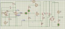
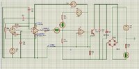
I’m new to circuit design and working on a 4-20mA 2-wire loop-powered system to convert a 0-50mV sensor output using the XTR116 (simulated based on the datasheet since I couldn’t find a library). I’m stuck on a couple of issues and need help:

  1. My sensor has a common mode voltage (50% of input). I added a voltage source at the AD623 input to simulate this. For 1-50mV inputs, I get 4.32-20mA output, which is great. But the AD623 output has an offset from the REF pin (tied to my simulated IRET). Oddly, the current through my 25kΩ resistors is always correct (e.g., 160µA at 50mV). Why is this happening?

  1. At 0mV input, the AD623 output doesn’t go to 0V due to the REF pin offset, so I get 7mA instead of 4mA. How can I fix this to ensure 0mV gives 4mA?

Thanks for any help!
 

Attachments

  • AD6235V_50mV_20mA.jpg
    AD6235V_50mV_20mA.jpg
    279 KB · Views: 24
  • AD6235V_1mV_4.32mA.jpg
    AD6235V_1mV_4.32mA.jpg
    222.9 KB · Views: 20
You may have to go with a rail-to-rail type instrumentation amp.
 
In my project, I’m designing a pressure transmitter, and I need the 0-50mV differential sensor output to map precisely to a 4-20mA current output for PLC. This is critical because any deviation could result in a loss of pressure measurement accuracy, which would affect the system’s performance. I understand that rail-to-rail isn’t exactly 0V but rather "nearish" to the rails, as you mentioned. However, I’m concerned that even a small offset might cause significant errors in my application. Is there an alternative way to design this circuit to ensure the 0-50mV input maps exactly to 4-20mA, without losing precision? I’d really appreciate any suggestions!
 
Something to try:
Add a diode (e.g. 1N4148) from the Ref pin to the negative rail to raise the IRET/U1Ref voltage for Ref and the op amp (-) input about 0.7V above the negative rail.
Add a 10KΩ resistor from the positive rail to the Ref voltage to provide bias current.
 
I use the XTR115, and the IRET is 0v referenced to the 2.5v output I run a precision op amp at 2.5 v.

I dont think your XTR116 is quite right.. the output stage on a real device has a darlington set up.

Without a "true" XTR116 part, your pretty much guessing.
 
I use the XTR115, and the IRET is 0v referenced to the 2.5v output I run a precision op amp at 2.5 v.

I dont think your XTR116 is quite right.. the output stage on a real device has a darlington set up.

Without a "true" XTR116 part, your pretty much guessing.
To improve my simulation and better understand the circuit’s logic before testing it in real life, is there a way to find a true SPICE model for the XTR116? Alternatively, do you have any suggestions on how I can simulate the XTR116 more accurately, especially considering the Darlington output stage? I’d really like to ensure my simulation aligns with the real device’s behavior as much as possible.
Thanks again for your help!
 

New Articles From Microcontroller Tips

Back
Top