Continue to Site

Welcome to our site!

Electro Tech is an online community (with over 170,000 members) who enjoy talking about and building electronic circuits, projects and gadgets. To participate you need to register. Registration is free. Click here to register now.

  • Welcome to our site! Electro Tech is an online community (with over 170,000 members) who enjoy talking about and building electronic circuits, projects and gadgets. To participate you need to register. Registration is free. Click here to register now.

Help with gain circuit for load cell

Status
Not open for further replies.
Hello everyone,
This is my first time using this forum so just let me know if I am going about this right. I am a second year engineering student.

So I need to build a gain circuit for the load cell for which I have included the data sheet. I would like to achieve the maximum resolution possible using this load cell as the application will be sensing forces in the range of 0-2.5 newtons.

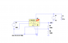
Currently I am running the system on a resistive force sensor (flexiforce) using a dual op amp LM358. This is because there is a separate function in the device in which this type of sensor is suitable. What I would like is to run both the load cell and the resistive sensor off the same 25V DC power supply. If this is not possible or if it is a lot easier to use two power supplies that is an option.

I appreciate any input and guidance.

Thanks,
James Lamarche
 

Attachments

  • load cell.pdf
    186.2 KB · Views: 625
What is the maximum output voltage that the load cell produces .... directly?
What is the maximum voltage that you require to be useful?
The ratio of these two values would be the overall gain that you would design for the op-amp.

The DC voltage supply for the force resistor would might be accomplished with a voltage regulator ... a separate issue.

When 12 volts are directly applied I get a max voltage of 6.442 mV across the load cell.

I am not sure what max voltage value I would need for it to be useful, I am using Labview as Data Acquisition software. From what I understand I need a large gain in order to get a higher resolution between these very small forces.


Does this make sense?
 
You will be doing DC voltage amplification for the load cell.
It would be helpful if you are able to use a circuit simulator.
Download the free simulator here:
Linear Technology - Linear Home Page
In the example section of the simulator is a circuit labeled op-amp integrator .
Open this example, and use the cut tool to remove the 58 µF capacitor.
The gain for this particular circuit is something like 2000, which may be useful for your particular data acquisition board. The gain value is adjusted by changing the value of R2/R1.

I couldn't find the circuit you are referring to, I found one labeled op amp but it has no 58µF capacitor so I don't think you are talking about this one. If it is possible do you think you could upload the circuit diagram you mentioned.

Thank you I really appreciate the help.

James Lamarche
 
So I could not find the circuit example that you mentioned. I found one labeled op amp, but it did not have a 58µF capacitor so I don't believe this is the one. If it is not too much trouble do you think you could upload the file? I would really appreciate it.


Thank you for all your help,
James Lamarche
 
Maybe you are looking in the wrong folder .... Op-Amp Integrator ought to be there.
Look in the general LTspiceIV folder.
 
Last edited:
Ive looked in every folder and I cant find it. I'm not sure why. I even tried just running a system search for the file name in case i missed it, but no results.
 
Last edited:
When 12 volts are directly applied I get a max voltage of 6.442 mV across the load cell.
Which load cell are you using?

I am not sure what max voltage value I would need for it to be useful, I am using Labview as Data Acquisition software. From what I understand I need a large gain in order to get a higher resolution between these very small forces.
You need to know what is the range of your input device 0 to 1volt, 0 to 5volts or ?? before you can calculate the gain required to amplify the 6 or so millivolts from the load cell.

JimB
 
Which load cell are you using?


You need to know what is the range of your input device 0 to 1volt, 0 to 5volts or ?? before you can calculate the gain required to amplify the 6 or so millivolts from the load cell.

JimB

I uploaded the data sheet in the first post. The excitation voltage range is 9-12 V .
 
Attached is one possible op amp circuit ... as shown the gain is about 100.
giving you a max output voltage of about 0.7 volts.
It seems to test out down to about 0.5 mV.
It is powered by a single positive 10 volt supply.

Does this meet your minimum requirements .... or is there something else?

..... Changing the ratio of R1/R2 will raise the gain up to 500.
However, a gain of 1000 seems to exceed the limits for this op-amp.
 

Attachments

  • load cell amp 01.PNG
    load cell amp 01.PNG
    22.3 KB · Views: 1,715
Last edited:
Status
Not open for further replies.

Latest threads

New Articles From Microcontroller Tips

Back
Top