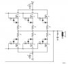
Hi all,
I'm using an LME49830 audio amplifier chip which serves as the input stage and voltage amplification stage for a power amplifier. It has outputs Nout and Pout which connect to the gates of a mosfet current gain stage. (see attached schematic).
I'm having a bit of difficulty constructing this output stage, as things have a tendency to blow up. I've gotten it functioning just great with a single output stage (one nmos, one pmos), but when I added a second stage (my wiring was correct to the best of my knowledge) the thing went up in smoke. This is a little frustrating, as I now have to replace all the power mosfets, the LME49830, and hope this doesn't happen the next time I power it on. On a side note, does anyone know some good remedies for this? I was considering placing a temporary fuse of very small value (maybe .5A) on each of the power supply rails to limit short circuit current.
Anyway--my main question. In the schematic that is attached, I left out the source resistors. Their typical value is from .1 to ~.2 ohms. Is this a no-no when using multiple output stages? Also, I left out the zener diodes that are shown -- these are purely protection devices, correct? That is, if they're 10V zeners, they limit the Vgs to +- 10V?
Thanks for any help or general advice!