Continue to Site

Welcome to our site!

Electro Tech is an online community (with over 170,000 members) who enjoy talking about and building electronic circuits, projects and gadgets. To participate you need to register. Registration is free. Click here to register now.

  • Welcome to our site! Electro Tech is an online community (with over 170,000 members) who enjoy talking about and building electronic circuits, projects and gadgets. To participate you need to register. Registration is free. Click here to register now.

Help with what is probably a very simple circuit

Status
Not open for further replies.

goaticus

New Member
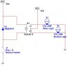
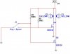
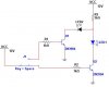
I am looking for an optional circuit to replace one I am currently using on my motorcycle. My current circuit uses an SPDT relay, but I would like to down size and physical relays are kind of bulky. Here is what the circuit does; When the key is turned on and the bike is in Neutral, the N light comes on. As soon as you put it in gear and the N light goes out, power from a separate 12V source is switched to a second light. This light then stays on even if the bike is placed back into Neutral. I wish I was as smart as you all so I could design things like this myself, but I am not. TIA, Jessie.
 
Last edited:
As you need something to remember that the neutral light has been on, you need a couple of transistors at least. Once those are on a circuit board and in a box, it's got to be nearly as big as a relay. I guess that even with a relay you will need a diode, but that is based on some assumptions about the circuit.

If your second light can be negatively switched, a thyristor would work, with a resistor to stop too much current going to the gate.
 
Below I attached a pic of the circuit I have now. It's pretty simple, but at over a cubic inch, the relay is pretty bulky.

headlight.GIF
 
Just a few nit picky comments on your schematic; I would first recommend that you add a resistor between the diode D1 and the base of Q1 in order to protect Q1 since it's a current controlled device and a diode does not limit current that much. Second, I would add a flyback diode across the coil of the relay for protection. Correct me if I'm wrong, but what you want to do is connect the circuit so that when you shift out of neutral, the neutral light goes out, then comes back on once you shift back to neutral?

Unfortunately there isn't really any other way to go about connecting the circuit as you described it, reason is the light bulb has a high current draw. A relay can easily handle this current, but there aren't a lot of other parts that can. Most general purpose NPN or PNP transistors are rated for 500mA or less. A 12V 10W light bulb will draw at least 800mA. The few parts that can handle the current for such a high current is usually a power transistor or some sort of power MOSFET. But then the heat sink for these parts would need to be large enough to dissipate the heat appropriately, which would make them even larger than the original relay.

However, if you are planning to use LEDs instead of a light bulb, that changes everything about this circuit. You no longer need a relay, and you can even use general purpose transistors which are 1/8 of a cubic inch. you can even make one LED display for both (using a bi-color LED).

I have attached some circuits that should clarify what I am talking about. The first one is a simplified circuit of what you have now. The second one is of a circuit that uses power MOSFETs to drive the light bulbs, remember, the heat sink needs to be able to disipate 10W of power or more for a 10W bulb. The third is of a simple circuit if you are using LEDs instead of a light bulb. I prefer to use the MOSFET or the LED approach over a relay because they physically last longer. Hope this helps :)

(P.S. Your circuit is latching the relay, remove D2 and R2)
 

Attachments

  • Motor cycle1.JPG
    Motor cycle1.JPG
    18.4 KB · Views: 182
  • motor cycle2.JPG
    motor cycle2.JPG
    16.7 KB · Views: 169
  • motor cycle3.JPG
    motor cycle3.JPG
    14.1 KB · Views: 159
Last edited:
Thanks, Dragon. The second light is a fairly high watt bulb so it looks like I will have to stick with the relay. For you nit-pick additions, how should I decide on the size for the additional resistor and could you be more specific (idiot-proof as I am not too savy) on the locations of the additional diode.
 
Last edited:
The resistor should be between 100R and 1k, you can go up to 10k only if you are using the transistor as a collector follower instead of an emitter follower. The diode needs to go across the relays coil with the anode to ground and the cathode to the signal source. (the diode's direction is the opposite of the current flow).
 
Status
Not open for further replies.

Latest threads

New Articles From Microcontroller Tips

Back
Top