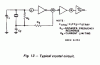
Continue to Site

Welcome to our site!

Electro Tech is an online community (with over 170,000 members) who enjoy talking about and building electronic circuits, projects and gadgets. To participate you need to register. Registration is free. Click here to register now.

  • Welcome to our site! Electro Tech is an online community (with over 170,000 members) who enjoy talking about and building electronic circuits, projects and gadgets. To participate you need to register. Registration is free. Click here to register now.

hi, need some help display

Status
Not open for further replies.
looks to me like pin12 is the reset and should be set accordingly, not necessarily ground?
 
Hi,
but can you say why it would not give the right FRQ on it
i did look on hear but could not find post on this problem??
 
Hi Kid-kv,

Your timebase, the CD4060 isn't working because it's reset function
is active. This is what the datasheet says about the reset:

"A RESET input is provided which resets the counter to the all 0's-state
and disables the oscillator. A high level on the RESET line accomplishes
the reset function."

There is a high level on the reset line, so change it to a low level.
And that's not all, there are two resistors missing, the oscillator is
probably working on another frequency.

on1aag.
 

Attachments

  • CD4060B oscillator.GIF
    CD4060B oscillator.GIF
    7.5 KB · Views: 203
Last edited:
hi on1aag
what would the resistors be in size or just use what the datasheet shows??

this is part of a tig welder circuit


thanks

kid-kv
 
Hi Kid-kv,

Start with one single resistor accross the crystal, use a 1 M and
see what it does. Later you can insert a 1 k resistor for Rs.

on1aag.
 
ok, that did not work if an ic was bad witch one do you think would it be?????
I put a dmm with a square wave out put of 50hz and it gave me 18 to 30hz so whats up guys ??????????

kid-kv
 
Hi Kid-kv,

The output frequency of the CD4060 should be 4 Hz. At the output(s)
of the first '112 you should measure 2 Hz and 1 Hz at the output(s)
of the second '112. If that's ok you should take a closer look at the
input signal, it should be at TTL level.

on1aag.
 
It is essential that you carefully check that what you built is exactly as the schematic shows. Check every connection and the actual value of every resistor and capacitor against the schematic. Once you have done that, here are some more ideas:

- if you are measuring 8 Hz at pin 3 of U3A, then your oscillator may be running at a harmonic (which is very unusual so I have my doubts about this) or you are simply measuring the output at pin 2 rather than pin 3. The values for C2 and C3 are good choices for this kind of crystal, but I do agree that a resistor across the crystal is necessary. I think your 3.9M should be fine. How is the circuit constructed? Is it built on a solderless breadboard, on a vectorboard pcb or on a custom pcb or something else? I ask because you have to minimize stray capacitance on the pins 10, 11 and 9. Solderless breadboard has way too much stray capacitance for this.
- that you are measuring 4Hz at U4B pin 7 indicates that U4A and U4B are working properly as their job is to divide by 4. I was a bit concerned that you might have substituted a CMOS IC at U4 which would require that all of those no-connect inputs be wired to either +5V or GND and not left floating. TTL will function correctly with inputs floating as we see here, although it is bad design practice to do so.
- I note that U5B has several inputs floating. This is unacceptable and may cause U5A to malfunction which would mess up the reset pulse to your counter chip. You should ground U5 pin 13 and pull U5 pin 11 to +5V, as required by the data sheet instructions.

If the only fault was that your time base is running at twice the expected frequency (that is, U3 pin 3 is outputing 8Hz instead of 4Hz), then your counter would always display values exactly half of what was expected. Is this the case? If the values jump all over the place and are not consistent, then I would also suspect something is wrong with the operation of U5A.

One other thing to mention is that this counter will only count signals that are large enough in voltage swing to toggle the input to U1A. I doubt that this IC is designed for small analog signals, so be sure that your inputs are swinging up and down from 0 to about 5volts or so. You should be able to measure your input's amplitude at around 1.5 to 2 volts ACRMS on a DMM. If you read a lot lower, then perhaps your simply not giving the counter enough input level. Its also worth mentioning that the input is expected to be a 0 to 5volt swing of voltage centered around 2.5 Volts. If you are AC coupling the input, you may not get correct function.
 
Last edited:
hi, RadioRon
I did look over the board and its ok..
the board is a custom pcb all leads are short that i did kept in mind when i did it..
will be back with more when done

Kid-kv
 
what if i took out the 4060 and used a 555 timer to get the 4hz would that work
the 22pf caps will not show up on my dmm as 0.022 nf

the display now shows 85hz to 100hz and did the pic of the board help??

Kid-kv
 
kid-kv said:
what if i took out the 4060 and used a 555 timer to get the 4hz would that work
the 22pf caps will not show up on my dmm as 0.022 nf

the display now shows 85hz to 100hz and did the pic of the board help??

Kid-kv


You could try this as a temporary experiment, but it is unacceptable as a permanent change because the oscillation frequency of the 555 will not be accurate or stable enough for good performance.

Before doing that, I would want to check that the counter portion of the circuit is working ok, that is, that U1 and U2 and the display circuits are all fine. If you can force U1 pin 10 and pin 13 low, then U1 should count up without stopping or resetting and continue to do so as long as you feed it an input at pin12. If your input is a low enough frequency then you should easily be able to see the displayed count increase in a readable way. One way to make the input signal toggle slowly is to connect up a button or toggle switch temporarily to ground and add a pullup resistor at the input. Pushing the button will provide a small number of pulses depending on how much switch bounce there is and so you should see the counter advance a few units.

If the counter is working fine, then we can turn our attention back to the timebase of U3 and U4. I would not suspect that the 4060 is blown. This is a common mistake made by novices, assuming that because things aren't working right the ICs are blown. They usually are not and usually the problem is a design mistake or a hookup mistake. I gather you don't have an oscilloscope handy. This is too bad as it would be quite helpful now.

The key is getting our oscillator in the 4060 to work right and its hard to check that without a scope. Have you already tried more than one crystal?

On the schematic, there are capacitors labelled C5, C6, C7, C8, and C9. Your board does not appear to include these. Why did you leave them out? These are important and should be placed very near each IC. You can add these by tacking them on to the underside of the board directly to the appropriate IC pads.

Of course it is critical that you be sure that your crystal capacitors be 22 pF, not 22nF or some other value.

The pic of the board is helpful, although your choice of colours is making it difficult. I would have recommended a white background, blue for IC outlines and bright green for all copper pads and traces. Labels are best left red, brown, violet or blue.

Are you available for skype chat?
 
Last edited:
kid-kv said:
hi, RadioRon
I did look over the board and its ok..
the board is a custom pcb all leads are short that i did kept in mind when i did it..
will be back with more when done

Kid-kv


Hmm, if the board is supposed to match the schematic, then I find these mistakes:

- C5,6, 7, 8, 9 are missing
- U4 pins 2,3,4,10,11,12 are grounded while on the schematic they are floating. U4A and U4B will not toggle in this case are so are not functioning. For these to function, pins 2,3,4,15, 10, 11, 12 and 14 should all be pulled to +5V (or can be left floating, but its not as reliable).
- your layout includes connections to U5 pins 11 and 13 which are not shown in the schematic. Happily, these connections repair a problem of incorrect hookup of the U5B which is a good thing, so in this case the layout is good and the schematic is bad. But why are they different?

As for the board layout, your circuit is vulnerable to noise problems due to the way you have connected up +5V and GND. It would have been better to run your ground traces in a hub-and-spokes configuration, where the hub of the ground is at the connector J1 and all the IC grounds return directly to this point or to a common bus bar. We use ground planes specifically for this purpose. Similarly, it is often better to distribute your +5V from a bus bar or from a single point to all ICs. You have connected +5 and GND in a daisy chain which is typically not so good. I wouldn't worry about it too much in this case for one exception. Since the CMOS ICs draw relatively small amounts of current when switching you may not suffer much trouble (once you add the missing bypass capacitors that is). However, the 4511 and the drive transistors are passing a lot of current (approx 15mA per segment of display) and they are being switched on and off at a rapid rate (the mux rate). This rapid switching of high currents will generate a noise voltage on +5 and ground that will be seen by the other ICs. This is a particular problem that you might want to fix. You should run the +5V to U2 all the way back to J1 on a separate wire from the other ICs, and run the ground from Q1,2,3 back to J1 separate from the other grounds. Bypass capacitors (C5..9 in the schematic) are critical to helping avoid problems due to this error.
 
Last edited:
On further examination of the pcb:

- I would have routed the connections to the two capacitors on the crystal a bit differently. In your layout, each capacitor's ground connection is long, adding some inductive reactance to the connection. Normally you should route these capacitor grounds directly back to the IC ground pin.
- I would not connect those copper pads around your mounting holes to your circuit ground. This creates a second path for ground currents to flow if you use a metal chassis and metal standoffs, which in principle can be a problem. You would normally want to insure that ground currents flow only through J1 to avoid ground loops. In your case it may not make a difference, but something to think about in future.
- exactly how have you modified the connection to the 4060 pin 12?

You know, I've spent a few minutes studying the logic of this counter and it doesn't make sense exactly. The time base appears to be designed to provide a gate time of 0.5 seconds minus the width of the one shot pulse which would be around about 5 mSec. This seems like sloppy design. This also means that the display will show approximately half the frequency in Hz. Why?

Normally a counter allows a gate time of precisely 1 second in order for the value in Hz to be displayed, and normally the reset logic is done outside of the gate time in such a way that you don't see it counting up during the gate time, you just see the latched result. This counter allows you to see it counting up. Exactly what is this counter supposed to be telling you about the TIG Welder?
 
Last edited:
hi, it does count up. And it does stop. I do think that it is the caps c2, c3.
i did use a oscilloscope and all looks good HP 1200A 500khz.
Have you already tried more than one crystal? yes watch crystal..
at first the crystal would not oscillat then when i put the scope on it then it would oscillat then i found out that it needed a resistor...
pins 2,3,4,15, 10, 11, 12 and 14 should all be pulled to +5V ok will do this with them to gnd it would stop at 000hz..
capacitors labelled C5, C6, C7, C8, and C9 You can add these by tacking them on to the underside of the board directly to the appropriate IC pads. i did that.
My best guest is that it would be the board....i say this becoz when i put my hand near it it flips out.

this is to show what frq that you are at when welding alu, sheet metal. helps make the arc more stable.

Are you available for skype chat? no =-(

Kid-kv
 
HI, RadioRon
I did some of what you said and now its off by 4hz..
I put a dmm with a square wave out of 50hz and it gave me 54hz
Thanks for the help

now i can fine tune the rest of the circuit

thanks

will come back when i need more help and will try to help out
kid-kv
 
Status
Not open for further replies.

Latest threads

New Articles From Microcontroller Tips

Back
Top