Electro Tech is an online community (with over 170,000 members) who enjoy talking about and building electronic circuits, projects and gadgets. To participate you need to register. Registration is free. Click here to register now.
Welcome to our site! Electro Tech is an online community (with over 170,000 members) who enjoy talking about and building electronic circuits, projects and gadgets. To participate you need to register. Registration is free. Click here to register now.
Thanks for the link !!! I love it....... Now how do I get the simulation ? I click run and expect to see a line showing on and off, maybe you can tell me what I did wrong. I really like this Spice tho, learned it fast too. Great for novices like me.
Several problems. The LED is backwards. Your timing capacitor was 10 FARADS. I changed it to 10uF.
To see the LED flash by making the 555 multivibrator have a defined duty cycle, you need the extra resistor in the timing network. I like to keep the timing resistors in a 555 circuit > 10K.
I didn't like your drafting style, so I moved thing around.
it works on my board but its my first time with spice, im thinking on taking some courses, i wasnt sure of the polarity of the led and the farads i want low, this circuit doesnt work but ive made oscillators with the 555's i just like using them. im an electrician 27 years and love controls and logic im an inspector as well but i have to hang up the tools because of my back, hip and knees, so since i enjoy electronics i thought that would be my new career. as far as my drafting, thats how we draft in the electrical trade, i see you dont draw all your grounds but just show a ground connection, i'll try it again
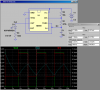
The ground symbols are all connected together. This is a shorthand method of decluttering the schematic drawing. Note the trick of "naming" wires (nodes) so that you can plot them by name. Also notice you can plot current through any component as well as node voltages. Further notice how I used "cursors" on the plot to show the voltages and time differences between the cursors.
This site uses cookies to help personalise content, tailor your experience and to keep you logged in if you register.
By continuing to use this site, you are consenting to our use of cookies.