Continue to Site

Welcome to our site!

Electro Tech is an online community (with over 170,000 members) who enjoy talking about and building electronic circuits, projects and gadgets. To participate you need to register. Registration is free. Click here to register now.

  • Welcome to our site! Electro Tech is an online community (with over 170,000 members) who enjoy talking about and building electronic circuits, projects and gadgets. To participate you need to register. Registration is free. Click here to register now.

How to adjust a Buck Regulator???

Status
Not open for further replies.

PhilipWarence

New Member
Good day.

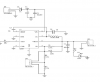
I have this Circuit using A8447. My output voltage is 5V.
My problem is I dont know where is(are) the divider resistor(s) to vary my output into 7.5V. Can somebody here help me how?
Also, do i need to remove the connection of Vbias and Vout if im going to target an output voltage higher than 5V?
TIA.
 

Attachments

  • smps.png
    smps.png
    53.6 KB · Views: 160
I should imagine Header 3 is for an external pot to vary the output voltage... Without the pot it is a fixed output..
But I don't know why there are three pins.. Maybe you can have three different ranges???
 
the data sheet says ;

VOUT. The output voltage is adjustable from 0.8 to 24 V, set by an
external resistor divider. The voltage can be calculated with the
following formula:
VOUT = VFB × (1 + R1/R2)
 
According to the data sheet the FB or feedback voltage is very close to 0.8V. And the calculation for the R1 and R2 is expressed by Vout=VFB(1+R1/R2). Using this formula I think there is a jumper connecting pins 1 and 2 of header 3. To change the output to 7.5 volts you need to change the values of R1,R2,and R3. The formula Vout=VFB(1+R1/R2) and be transposed to:
R1=(Vout/VFB-1)R2
 
Last edited:
Yes its the FB pin resistors...but you are better off to bring the error amplifier outside the chip , and vary the reference to the error amp than switch resistors in and out.
 
Hi

I don't think the schematic is correct. Here's a schematic that shows the way I think you want to configure the headers.
Also, VBIAS has a max input of 7v, so...only connect it if target output is between 3.3v-5v (as stated on the datasheet)

eT
 

Attachments

  • A8447BuckReg.png
    A8447BuckReg.png
    76.7 KB · Views: 150
Last edited:
Status
Not open for further replies.

Latest threads

New Articles From Microcontroller Tips

Back
Top