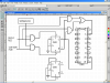
Continue to Site

Welcome to our site!

Electro Tech is an online community (with over 170,000 members) who enjoy talking about and building electronic circuits, projects and gadgets. To participate you need to register. Registration is free. Click here to register now.

  • Welcome to our site! Electro Tech is an online community (with over 170,000 members) who enjoy talking about and building electronic circuits, projects and gadgets. To participate you need to register. Registration is free. Click here to register now.

how to build a 3digit up/down counter w/ separate inputs?

Status
Not open for further replies.

poi

New Member
hello! i really need help :( in building a 3-digit up/down counter w/separate inputs for up & down counts, and the output is shown in the 3 digit 7-segment display. also, the counter should be presettable to a certain number... :wink:
how can this be done? :shock:
please help!
thanks very much!!! :D
 
1 - PIC16F84A Microcontroller
1- 7447 - BCD to 7-segment decoder
1 - 7442 - BCD to 1-of-10 decoder
- or any 2 to 4 decoder ICs
3 - 7-segment Common anode

- Use the 7442 or any 2 to 4 decoder to select any of the 3 7-segments
- by programming the PIC, select one 7-segment at a time at a very fast pace making the 3 7-segments appear to be simultaneosly lit.
- the 7447 will be used to convert BCD to its 7-segment equivalent
- 2 pins of the PIC will be used for column selecting/scanning, 4 pins for the BCD to 7 segment conversion
- 3 pins can be used for push buttons - up, down and reset

hope this will help you.
 
If you want to do it without a micro, this is one way:
 

Attachments

  • count_down_up_212.png
    count_down_up_212.png
    59.8 KB · Views: 2,391
There have been many counters discussed in the forum in the past.

Do a search on counters.

You won't learn if we do it for you.
 
thanks!

i found a counter in Laurier's page... it's quite suited to my needs... thanks a lot guys! anyway, just have a little difficulty in multiplexing the 3 7-segment displays...is it right to connect the collector leads to ground and pin 6(dp) of the 7-segments to ground? the circuit is attached...

thanks again!
 

Attachments

  • 3d.gif
    3d.gif
    9.4 KB · Views: 1,861
Re: thanks!

poi said:
i found a counter in Laurier's page... it's quite suited to my needs... thanks a lot guys! anyway, just have a little difficulty in multiplexing the 3 7-segment displays...is it right to connect the collector leads to ground and pin 6(dp) of the 7-segments to ground? the circuit is attached...

thanks again!
You did not specify the ICs, so I don't know what pin 6 does.

It is evident that the 7 segment decoder outputs the high level and so the multiplexing can be done with PNP transistors with their collectors connected to gnd as shown. But again, you did not specify the counter IC so I can't be sure.
 
Russlk said:
If you want to do it without a micro, this is one way:
Why are you showing a circuit requiring an astable input?

Poi,
Play with the 74HC191 counters.
The 74HC191 is a 4-bit up/down Binary counter. Once you figure out how it works (use a simulation program), connect a 7447 or 74247 to the binary outputs.

So all you really need for each digit is:
a 74HC191 counter (or equivalent)
a 7447 or equivalent BCD to 7-segment decoder
a set of logic gates to filter the inputs and outputs to your needs.

Multiply the above recipe by 3, and you are done.
 
The 74XX192 is a decade up/down counter, which simplifies the counter, and it has separate up and down clocks, which is a requirement.
 
astable means oscillates.

so an astable multivibrator is an oscillator.
 
Oh, I see. The high frequency clock is needed because there has to be a delay between switching the 4510 from down count to up count and clocking it. The input count pulse has to be wider than the delay or this circuit doesn't work. The high frequency clock only needs to be several times faster than the input count rate.
 
The gates could be eliminated by using a JK flip flop. Connect the HF clock to the clk input, the up pulse to the J and the down pulse to the K.

Alternatively, the HF clock eliminated. Simply connect the up clock to the Set input and the down clock to the down input.
 
hey guys! i finally have a working counter! thanks a lot for all your ideas! i used a 4510 bcd counter & 4511 7-seg decoder... the counter is working fine when i use manual switching but it skips a number or two when i use a relay from a light sensor as my input pulse... any suggestions? gracias!
 
poi said:
.. the counter is working fine when i use manual switching but it skips a number or two when i use a relay from a light sensor as my input pulse... any suggestions? gracias!
This is due to "contact bounce". When switch or relay contacts open or close, they generate numerous brief opens and closes called "bounce".

To prevent this you need a "bounce suppressor" This has discussed many times in this forum. If you search on "bounce suppressor" you will find several circuits that will do the job. If you read the threads you will learn more about the subject.
 
Hi poi,

I guess all those suggestions were not what you really want.

As I understand you are a newcomer and you are searching for a complete circuit.

Here is one classic design counting up and down with BCD switches to preset the required counts.

(The preset is shown for the LSB in my design. Other presets have to be wired the same way and connected to the 'load' switch. When toggling the switch the counter stops.)

The circuit design is not perfect since there is no logic circuitry involved stopping the counter at overflow. It will continue counting either reaching count 000 or 999 depending on the direction of count.

All the best.

Boncuk
 
Last edited:
Status
Not open for further replies.

New Articles From Microcontroller Tips

Back
Top