Continue to Site

Welcome to our site!

Electro Tech is an online community (with over 170,000 members) who enjoy talking about and building electronic circuits, projects and gadgets. To participate you need to register. Registration is free. Click here to register now.

  • Welcome to our site! Electro Tech is an online community (with over 170,000 members) who enjoy talking about and building electronic circuits, projects and gadgets. To participate you need to register. Registration is free. Click here to register now.

how to decrease or kill the resonance of a filter design

Status
Not open for further replies.

caga

New Member
Hi to all,

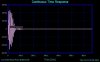
I am trying to design a LC band-pass filter like the one in pic1. The resonance frequency is 120kHz with a pass-band of 20kHz. The problem is after each peak the system is resonating and lots of decreasing peaks occur until the other peak comes. The clear signal should have only peaks not the resonated ones.

Do you have any idea? maybe the design is wrong? I means the values...
 

Attachments

  • pic1_159.jpg
    pic1_159.jpg
    10.2 KB · Views: 681
My sim shows that the bandwidth is closer to 53kHz.
What does the input signal that is causing the ringing look like?
 
A PNP transistor is driving the filter as Tx, just before the 47nF cap. After the transmission line there is another filter which have the same values. When I look the received signal with a scope I see the ringing. I also try to change the receiver part to be sure that the Tx is making the ringing, nothing changed so I doubbed the conclution.

53kHz bandwith is strange, which program are you using? I am triying to learn "filter solutions". After giving the values I changed some values in order to standardize them. Maybe I am doing something wrong?
 
caga said:
A PNP transistor is driving the filter as Tx, just before the 47nF cap. After the transmission line there is another filter which have the same values. When I look the received signal with a scope I see the ringing. I also try to change the receiver part to be sure that the Tx is making the ringing, nothing changed so I doubbed the conclution.

53kHz bandwith is strange, which program are you using? I am triying to learn "filter solutions". After giving the values I changed some values in order to standardize them. Maybe I am doing something wrong?

I'm not sure how I got 53kHz. Now I get 62kHz. :oops:

Can you post a complete schematic, including the PNP and it's associated circuitry?
What is the nature of the signal that is causing the ringing?

I used Linear Technology's SwitcherCAD III, which is free.
 

Attachments

  • 128khz_bpf_waves.gif
    128khz_bpf_waves.gif
    14.8 KB · Views: 637
  • 128khz_bpf_sch.gif
    128khz_bpf_sch.gif
    8 KB · Views: 692
Sorry it took a while to draw it.
I want to post the schematic but I dont have any easy drawing software, the PCB will take hours to do. By the way do you know one?

Please think that 2 of this circuit is in place. As I said I changed one parts Rx to test that ringing is from the Tx.
 

Attachments

  • filter1.jpg
    filter1.jpg
    45.4 KB · Views: 625
I forgot to write that the impulse lasts 104uS each, every 5seconds.

Also I found this graph within the filter design program:

According to this graph there must be ringing apprx 50uS long !!! I am lucky that mine lasts only 8uS :lol:
The period of 120Khz is app 8.3uS , new peak comes.
 

Attachments

  • filter_impulse.jpg
    filter_impulse.jpg
    31.8 KB · Views: 607
Well, the second circuit you posted is different from the original one. You have me really confused. You are even driving it at a different point.

If you drive the NPN with a 120kHz square wave, you should get a fairly clean sine wave out. What does the graph you posted have to do with that? What signal are you really going to apply from the PIC?
What are you really trying to do? It looks like power lines (mains) communication.
 
Narrow-band tuned circuits cause ringing. Even an ordinary more than one stage Butterworth lowpass or highpass filter causes some ringing.
If you don't want ringing then don't use a sharp filter.
I think a Bessel filter doesn't ring, because its response drops off gradually.
 
Thank you audioguru I will try that.

Ron, actually it is not different. In the first one there are resistors for the source and load. An approximation of cource. In this circuit, the output of the npn and the pnp tr's have a clean sharp square wave, as it is also at the output of the PIC.

Yes it is powerline communication. The graph is only a simulation of the filter design software, nothing real. But I see a similar impulse when I look at with a scope to the circuit.

The only aim is to transfer a clean signal (a burst) of 120kHz between pairs of TxRx. I am ready for different ideas also :shock:
 
caga said:
The only aim is to transfer a clean signal (a burst) of 120kHz between pairs of TxRx. I am ready for different ideas also :shock:

As I mentioned in the previous thread, this was always done using a transformer, with the untuned low impedance primary connected to the supply line (via the usual blocking capacitor), and the high impedance tuned side feeding the receiver. Just like an IF transformer!.
 
Thanks Nigel, I agree with your opinion.
I found and tried AM transformer, and it worked pretty well.
I am trying to save some components, finding some components even for testing is not so easy. To save some components and space I trying to build it only with capacitor and inductors.
 
caga said:
Thanks Nigel, I agree with your opinion.
I found and tried AM transformer, and it worked pretty well.
I am trying to save some components, finding some components even for testing is not so easy. To save some components and space I trying to build it only with capacitor and inductors.

The transformer also gives you gain, it's a far more elegant solution than trying to bodge a filter together, where you will have to add extra active components to make up for it - you might have perhaps noticed?, radios are never built in that way!.
 
Status
Not open for further replies.

Latest threads

New Articles From Microcontroller Tips

Back
Top