Marco Aurelio Villarreal
New Member
Good evening people from Electro-Tech-Online.com:
This is my first post here, I'm Marco and I'm a mechatronics engineering student. Today I would like to detail my issue on how to implement a control system in real life:
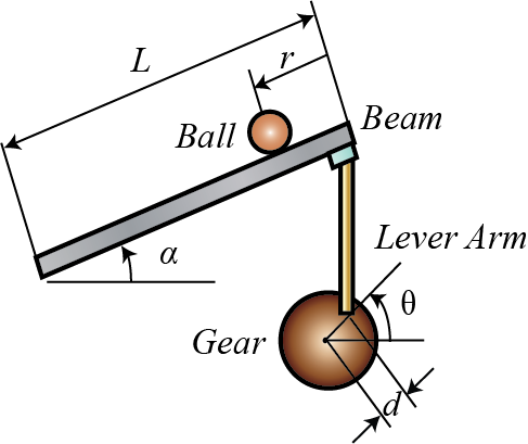
To begin with, I would like to mention an example that many beginners in control work with: the ball and beam system. I have to say at first that this is a classic example since it allows students basic concepts of control (e.g. designing PID controllers, studying frequency response, analyzing stability, among others). Its schematic appears in the image below:

Ball and beam systemThis is the website that I took the example from:
The site takes an approach on working with it: modelling (i.e. finding the dynamic equations and its representations in transfer function and state space form), open-loop response, closed-loop control in MATLAB (i.e. PID controller design, root locus, frequency response, et cetera), and analyzing the block diagram as well as studying open-loop and closed-loop response in Simulink.
Now I want to implement it. Build something similar like this:
 I've seen many people using elements like an Arduino board and an ultrasonic sensor that feeds the output to the Arduino, as well as a servomotor that acts as input. The thing is on how do they relate the transfer functions (or state space) to the actual physical system? I wonder this since there can be other elements with complex behaviors like h-bridges, motor drivers, filters, et cetera that were not modeled in the schematic. How do they model that? What if instead of an ultrasonic sensor they used an LVDT or a capacitive sensor to measure distance, how do they model that if it was not on the schematic that I have previously shown? Would that change the maths?. What are the steps that as an engineer one must take in order to implement closed loop control on a real system? I know that the PID control is being run as code on the Arduino board (it could also be implemented using opamps or any other microcontroller).
I say this because the ball and beam system is not the only dynamic system, there are many other systems to control like the inverted pendulum, servovalves, planar mechanisms (e.g. robotic manipulators), liquid level systems, or many many others. Obviously the materials involved would change, but how to relate the maths of MATLAB and Simulink to real life? I wonder this because there are plenty of documentation in the internet yet they never go on the building of the real example (i.e. they just work with MATLAB and Simulink) and I don't want just to copy others' ideas on how to implement the system (what if I didn't have an ultrasonic sensor and instead I had to use other type like an encoder or something similar?). I would appreciate your answers, thanks.
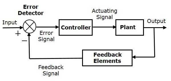
PD. I know that the basic structure of a closed-loop system is:
 The controller would be the Arduino, the plant is the ball and beam system (including motor), the feedback elements would be the ultrasonic sensor and the error detector would be part of the Arduino. Where do other elements like signal conditioning circuit for the sensor, the h bridge (or any other driver) of the motor fit in?
This is my first post here, I'm Marco and I'm a mechatronics engineering student. Today I would like to detail my issue on how to implement a control system in real life:
To begin with, I would like to mention an example that many beginners in control work with: the ball and beam system. I have to say at first that this is a classic example since it allows students basic concepts of control (e.g. designing PID controllers, studying frequency response, analyzing stability, among others). Its schematic appears in the image below:

Ball and beam system
The site takes an approach on working with it: modelling (i.e. finding the dynamic equations and its representations in transfer function and state space form), open-loop response, closed-loop control in MATLAB (i.e. PID controller design, root locus, frequency response, et cetera), and analyzing the block diagram as well as studying open-loop and closed-loop response in Simulink.
Now I want to implement it. Build something similar like this:

I say this because the ball and beam system is not the only dynamic system, there are many other systems to control like the inverted pendulum, servovalves, planar mechanisms (e.g. robotic manipulators), liquid level systems, or many many others. Obviously the materials involved would change, but how to relate the maths of MATLAB and Simulink to real life? I wonder this because there are plenty of documentation in the internet yet they never go on the building of the real example (i.e. they just work with MATLAB and Simulink) and I don't want just to copy others' ideas on how to implement the system (what if I didn't have an ultrasonic sensor and instead I had to use other type like an encoder or something similar?). I would appreciate your answers, thanks.
PD. I know that the basic structure of a closed-loop system is:

Last edited:

