soulsurfing
New Member
Hey all,
First post here. I am looking for some suggestions on how to do this. I am looking to hook up a set of lights, that will need to give me a visual readout from the room next door. I will not be able to see in the rooms where the lights will be lit up, hence the visual LED readout. The input voltage will be between 12 and 15 volts, and can change at any time in between this range.
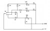
First, I will have a Master Arm switch which will activate all other switches which will provide power to the lights and flasher itself (ARM Switch will need to handle about 30 Amps). I would like to outfit this arm switch with 2 LED's. When the ARM switch is off, I would like a red LED to be on, when the ARM switch gets activated, the red LED is to turn off and a green LED is to turn on. When the ARM switch is active (green LED is on, red LED is off), it needs to provide current to my 7 other switches. These toggle switches (1ON-OFF-2ON), 2 total, will be laid out similar but slightly different. I'll describe what I want each switch to have do. When the switch is in the OFF state, a separate from above red LED needs to be active. When in 1ON state, 1 green LED will be active, when in 2ON state, 2 green LEDS need to be active. Each "mini-circuit" will have its own set of 1 red LED and 2 green LEDS (which light up different, depending on the state of the toggle switch). I hope this makes sense. Each circuit needs to be able to handle a current ranging from 5 Amp to 15 Amp continuously. The LEDs are only to indicate the status of the switch, the actual lights will be a separate load on the same switch.
I have a decent understanding of electronics and will be able to figure it out someday when nudged in the right direction. I searched the forums, and found nothing related to the way I want my switches with LEDS to act. I know that I could use a DPDT relay, but would prefer to not needing several relays to accomplish this goal. I would like to keep my project as small as possible.
First post here. I am looking for some suggestions on how to do this. I am looking to hook up a set of lights, that will need to give me a visual readout from the room next door. I will not be able to see in the rooms where the lights will be lit up, hence the visual LED readout. The input voltage will be between 12 and 15 volts, and can change at any time in between this range.
First, I will have a Master Arm switch which will activate all other switches which will provide power to the lights and flasher itself (ARM Switch will need to handle about 30 Amps). I would like to outfit this arm switch with 2 LED's. When the ARM switch is off, I would like a red LED to be on, when the ARM switch gets activated, the red LED is to turn off and a green LED is to turn on. When the ARM switch is active (green LED is on, red LED is off), it needs to provide current to my 7 other switches. These toggle switches (1ON-OFF-2ON), 2 total, will be laid out similar but slightly different. I'll describe what I want each switch to have do. When the switch is in the OFF state, a separate from above red LED needs to be active. When in 1ON state, 1 green LED will be active, when in 2ON state, 2 green LEDS need to be active. Each "mini-circuit" will have its own set of 1 red LED and 2 green LEDS (which light up different, depending on the state of the toggle switch). I hope this makes sense. Each circuit needs to be able to handle a current ranging from 5 Amp to 15 Amp continuously. The LEDs are only to indicate the status of the switch, the actual lights will be a separate load on the same switch.
I have a decent understanding of electronics and will be able to figure it out someday when nudged in the right direction. I searched the forums, and found nothing related to the way I want my switches with LEDS to act. I know that I could use a DPDT relay, but would prefer to not needing several relays to accomplish this goal. I would like to keep my project as small as possible.