Continue to Site

Welcome to our site!

Electro Tech is an online community (with over 170,000 members) who enjoy talking about and building electronic circuits, projects and gadgets. To participate you need to register. Registration is free. Click here to register now.

  • Welcome to our site! Electro Tech is an online community (with over 170,000 members) who enjoy talking about and building electronic circuits, projects and gadgets. To participate you need to register. Registration is free. Click here to register now.

How to minimize undershoot while generating a high voltage square pulse with MOSFET

Status
Not open for further replies.

ssmsky

New Member
Hello,

I have built a circuit to give me a high voltage (0-150 V) pulse with adjustable pulse width (2-20 micro s) by discharging a capacitor via a MOSFET whose gate is controlled by a 5V signal with required pulse width. The circuit schematic is attached.

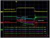
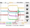
When I attach a 1 Ohm load, supply 75V DC from the power supply and measure voltages at points A, B, C and G with respect to ground, I see a voltage pulse across the load (point B & C) as shown in the oscilloscope image attached. The voltage pulse between B and C is shown with Math channel in red color.

However, I also observe an undershoot at the end of the pulse (Math channel in the image) and some ringing. Can anybody help me explain what may be causing such a large undershoot ? I am expecting voltage difference between B and C to drop to zero once the gate signal (G) is switched off. I am not very much concerned about ringing that follows the undershoot, but I would also like to know ways to minimize it.

Thanks,
 

Attachments

  • Pulse Generator Ckt.PNG
    Pulse Generator Ckt.PNG
    28 KB · Views: 551
  • Pulse Generator Measurement.PNG
    Pulse Generator Measurement.PNG
    66.2 KB · Views: 370
Your signal source says 200kHz, but the plotted pulse width is 10usec. What is your real input frequency?

BTW, your transistor is specified for Vgs=10V. Why are you only driving it with 5V? Your on resistance will be undetermined.
Also, your transistor is rated for 100V max. What is the actual value of V1?
 
Last edited:
Your "over/under shoot" may have to do with the area of your project. Keep the wires short! Keep the ground lead on your scope short.
 
The voltage you are witnessing would be caused by inductance in your load. As ronsimpson wrote, you should keep your wires short. You can decrease the magnitude of the spike by connecting a freewheeling diode across the 1k resistor (cathode to B, anode to C).
 
Thanks for the reply. I wish to obtain only single pulse whose width I wish to vary with my gate signal. The clock in the schematic is just a representation. I want the pulse width between 2 micro seconds to 20 micro seconds. The measurements are shown for 10 usec.

The DC voltage supplied to the bridge rectifier was 75 V and I am using 5 V gate signal. I guess I should be using 10 V to drive the gate.
 
The voltage you are witnessing would be caused by inductance in your load. As ronsimpson wrote, you should keep your wires short. You can decrease the magnitude of the spike by connecting a freewheeling diode across the 1k resistor (cathode to B, anode to C).

Is freewheeling diode just a normal diode connected in parallel?
 
I connected a freewheeling diode (I had a 6A05 diode) parallel to the load as well as parallel to drain-source terminals of the MOSFET. I changed my gate signal to 10V instead of 5 V, which improved the voltage across B-C. However, I still see the undershoot (image attached).

Am I using a wrong diode ? Is there any way I can calculate the requirements for the freewheeling diode ? or perhaps use any other method ?
 

Attachments

  • 75V_10us_1OhmLoadwithDiode_10Vtrigger.jpg
    75V_10us_1OhmLoadwithDiode_10Vtrigger.jpg
    42.1 KB · Views: 257
Only a guess, but is the 1 ohm resistor (R2) wire wound? If so it will want a diode as well.
 
Status
Not open for further replies.

Latest threads

New Articles From Microcontroller Tips

Back
Top