Continue to Site

Welcome to our site!

Electro Tech is an online community (with over 170,000 members) who enjoy talking about and building electronic circuits, projects and gadgets. To participate you need to register. Registration is free. Click here to register now.

  • Welcome to our site! Electro Tech is an online community (with over 170,000 members) who enjoy talking about and building electronic circuits, projects and gadgets. To participate you need to register. Registration is free. Click here to register now.

I need a special Switch and dont know where to get it from...

Status
Not open for further replies.

wireaudio

New Member
Ok this is what im trying to do:

Apply a 20ma (max) 5v signal to a line. When that gets applied, switch turns on and lets 12V to flow through.

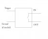
Here's a little diagram:

switch-jpg.24489


Basically the TRIGGER i have is 5v 20ma and when i apply that to it, i want to activate the switch between IN and OUT (to basically allow that to flow).

The IN i need either a 12/24V DC or AC, or 120V AC.

Thanks :)
 

Attachments

  • switch.jpg
    switch.jpg
    13.5 KB · Views: 222
No, the 5v/20ma (well 25ma MAX to be more exact) is the output from a pin on a PIC16F688 microcontroller. I want to use that output to controll a door strike module. So the 5v would be applied whenever the door needs to be "opened".

Maybe i didnt explain this right. I want the switch to CLOSE as long as i apply the trigger to it, and be left open otherwise.
 
Last edited:
Well, the details help us to help you.
So you need a one shot, I think, triggered by the microcontroller.
Pulse has to be long enough for the door mech. to do it's job.
Or the pulse width is controlled by the microcontroller?
 
I was thinking of making my own "switch" with a transistor and applying that 5v/20ma to the gate :p But i started simulating and it started to get more and more complicated... figured a relay or switch pre-build would be easier.
 
"switch turns on and lets 12V to flow through."

"The IN i need either a 12/24V DC or AC, or 120V AC."

I think it's best if you decide if it will be 12vdc or 24vdc or 120vac.
 
Last edited:
I can work with either. Theres a few latches there that work with 12/24 AC OR DC and a few that work with 120V AC. I really dont care what latch i use, as long as it works with my setup.
 
Please provide the exact part number of the latch you intend to use. Better yet, give us a link to the data sheet.
 
This might be useful. I'm not an engine ear.

Yeah, the above relay is a better solution but this was good practice for me.
 

Attachments

  • door latch trigger.gif
    door latch trigger.gif
    4.5 KB · Views: 107
Last edited:
One solid state relay, 600mA, up to 60V, controls are TTL/CMOS levels, SIP-4, SPST-NO:
Digi-Key - CLA274-ND (Clare - CPC1218Y)
$2.15, single quantity.

If this doesn't do it for you, search DigiKey using "solid state relay". Be sure to use the "In Stock" button to get the search down to 1,200 parts.

Happy holidays!
kenjj

That's awesome! Thank you!

Another quick question, how can i tell if the controlls are TTL/CMOS levels?
 
This relay fires up at 3.75V, dies at 1V. TTL levels are 0-0.8V for a low (relay off), 1.8V-5V for a high (relay on at 3.75).
CMOS is based on the Vdd you're driving the chip at. A low is <= 45% of Vdd, a high is greater than 45% Vdd. So, with CMOS, if your Vdd is 5V, a low is anything less than 45% of 5V (0-2.25V), a high is anything higher than 2.25V.
A PIC is TTL and CMOS compatible, so if you are using a Vdd of 5V, you're good to go. If you're using 3.3V or less, you're up the river.

Later!
kenjj
 
Status
Not open for further replies.

Latest threads

New Articles From Microcontroller Tips

Back
Top