Continue to Site

Welcome to our site!

Electro Tech is an online community (with over 170,000 members) who enjoy talking about and building electronic circuits, projects and gadgets. To participate you need to register. Registration is free. Click here to register now.

  • Welcome to our site! Electro Tech is an online community (with over 170,000 members) who enjoy talking about and building electronic circuits, projects and gadgets. To participate you need to register. Registration is free. Click here to register now.

IFT alignment of old transistor AM Radio

Willen

Well-Known Member
Hi,
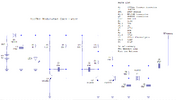
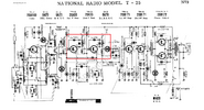
I have an old radio from National Panasonic, almost the same as the attached schematic. Mistakenly IFT of the radio are wrongly adjusted. I searched a few articles and most of them suggest making an AM-modulated 455KHz frequency generator and aligning the IFT to get a modulated AM tone louder. Currently, I aligned the IFT just tuning a station and, with louder audio output. Is it a satisfactory method or do I need a 455KHz AM-modulated frequency generator?

Another, If I tested the collector pin of the IFT transistor with an oscilloscope, can I see the 455KHz +/- waveform? (I don't have an oscilloscope but I can manage to test with help.) My 20MHz multimeter showing nothing.
 

Attachments

  • AM Panasonic Radio 7 transistor.png
    AM Panasonic Radio 7 transistor.png
    217.5 KB · Views: 80
Last edited:
Why did someone misadjust the transformers? - it's something you NEVER need to touch.

You're probably fine adjusting it just using a radio station - however, you've no idea what actual frequency you're adjusting it to, that's why you're supposed to use a signal generator. Use a weak radio station though.

A scope is of little use, as the signals are really VERY low, and a meter is of course useless.

What you could use, is an analogue meter on the AGC line, which gives you an accurate representation of the signal strength - a digital meter is pretty poor for doing this though.
Hi, Sorry that the radio is 40 years old, older than me. Years ago I was looking inside to get magic. Maybe that time I misadjusted these IF transformers. I do not use the radio much but sometimes SW and MW attract me as amateur radio hobby. And now I realise that what I did in the past with their accurate and sensitive IF transformers.

OK, I will now make a simple 455KHz AM modulated circuit as I attached. It has an RF transmitter antenna. So maybe I should place the circuit near the AM radio. Then do I need to tune the IF transformer for louder audio output (generator transmits 500Hz or something like that tone with 455KHz carier), for a simple method of tuning? (instead of analogue rare DVM or digital meters) Or need to inject the 455KHz signal to the base of IF transistor?
 

Attachments

  • 455Khz_Modulated_Oscillator_redrawn_schematic.png
    455Khz_Modulated_Oscillator_redrawn_schematic.png
    30.2 KB · Views: 55
You would normally inject it at the input to the IF chain, at a very low level, and adjust for the highest voltage on the AGC line - the service manual for a set of that era will tell you the exact procedure.

I've never had occasion to align a radio IF chain, but I did once realign a TV IF chain, where the idiot customer brought it in and said "I tightened all those loose screws down, and now it doesn't work". Needless to say, I give him a big bill :D

TV is a lot more complicated though, and I had to use 'spot' frequencies, from an ancient ex-WWII signal generator - the preferred method would be to use a wobbulator and oscilloscope (as it would be for your radio).
 
Each IF transformer is a "double'tuned" BPF.
So imagine you can adjust the mutual coupling between a two-humped camel and make one hump bigger or the other or spread them apart.

Ideally the IF for 455 kHz AM filter will have at least 15 kHz BW to demodulate to 50% of this in baseband with an equivalent low ripple between the humps which gives steep skirts of rejecting the adjacent channel. But misaligned will sound like an EQ filter of some random shape.

So louder is better, but may have a skewed EQ ( reduced BW or accented treble) rather than flat maximally EQ of 7.5 kHz (If I recall)

A wobulator must be a sign gen. with an FM sawtooth fixed carrier to generate the largest flat spectrum for IF out from the burst cycle calibrated for AM. Another idea would be an AM multi-harmonic (pulse) with FM slow wobble to flatten the resulting sound or image on a scope. When FM wobbles on the edge of a steep filter, that produces AM noise so if no AM modulation was generated, FM wobble would sound like AM wobble from your filter ripple which you might want to minimize while tuned near center 455 kHz +/-3 kHz for the humped camel.

Then repeat for the 2nd double-tuned stage filter.

As you may appreciate by now, it's best left up to the retired Japanese Techs at Panasonic and would only change if dropped at a certain angle and height with the wax breaking bond.

But if you can generate an AM sweep generator very accurately at 455 kHz with a 8~10 kHz deviation pk-pk you want the maximum gain yet the minimum wobble on a 2 humped camel and symmetrical 30 to 45 dB rejection +/-10 kHz depending on your tradeoffs for selectivity and EQ distortion
e.g.
1715702036931.png

1715701835846.png
 
Last edited:
CORRECTION This tuning guide says to use 8kHz -3dB BW, for 5kHz baseband audio ( not 15kHz/7.5) Is that still true for stereo AM? https://www.nutsvolts.com/magazine/article/build-a-vintage-radio-sweep-alignment-instrument

These 4th order filters are designed to maximize attenuation of ACI (adjacent channel interference) that might be 40+ dB or more stronger than the faint channel you are trying to hear. This where the filter specs are critical at alignment to reject 455kHz +/- 10 kHz yet not be due to merging the two humps together and reducing the audio BW. If you are good at tuning you might get 30 dB ACI rejection, and if great like a Japanese tech tuner, 40 dB with a quad humped low ripple Chebychev filter in this simple 8th order BPF filter with only 2 tuning slugs that shift slug to control coupling from one coil to the other.

Then it starts to look like a Bart Simpson's haircut with something dB ripple which is always designed by the Q or R/L load damping ratio.
1715703992608.png


Or a Bessel filter with smooth audio but poor ACI. (20 dB/div)
1715704132878.png

Or a Butterworth filter, which is a Chebyshev filter with 0.0 dB ripple
1715704270480.png

So tune your IF on the weakest AM signal surrounded by strong neighbours. I used to tune my old radio for more treble by a small offset on the main tuner and thus shift the LO.
 
Last edited:

Latest threads

Back
Top