ElectroUser
New Member
Hi,
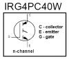
I am using an IGBT for experimental purposes. I am using Intenational rectifiers IRG4PC40W rated at 600V 20A on a simple resistive load. Using an 220 Ohm gate resistor i am getting a 80V overshoot with 20V Vce and 2A Ic. Can someone enlighten me why am i getting such a big overshoot. Can it be the circuit board? I have tried to keep the connections as short as i can but will a better circuit board reduce the overshoot?
Thanks in advance.