ranatungawk
New Member
Hi friends; ")
I'm struggling with a mystery issue. Please help me by giving your expert comments on this….
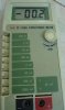
I'm troubleshooting somewhat old "YF-1150A" capacitance meter. When I received it didn't work at all. I found some signaling transistors got burnt. Having replaced them, I was able to fix major issues and now it's reading is almost correct. However, after 3,4 hours of repairing , the meter's idle value is changed to -00.2,-00.2…-0.4 (idle value should be 00.0 when any button is not pressed.).
The mystery I found was this, when the idle value is changed (to -00.4 or -00.6) If I remove some parts (ex: transistor, capacitor..) from the PCB and resold them again as they were on the board, idle value comes to "00.0" again. but after 2,3 hours it go wrong as it was.
So I thought this can be a result of a "bad capacitor" somewhere in the PCB. so I replaced all caps and checked all transistors. But the issue remains same.
This meter circuit is based on The ICL7106 A/D converter. Please see the diagram and pics I have attached herewith. Could you please let me know what should I check…
Thanks
I'm struggling with a mystery issue. Please help me by giving your expert comments on this….
I'm troubleshooting somewhat old "YF-1150A" capacitance meter. When I received it didn't work at all. I found some signaling transistors got burnt. Having replaced them, I was able to fix major issues and now it's reading is almost correct. However, after 3,4 hours of repairing , the meter's idle value is changed to -00.2,-00.2…-0.4 (idle value should be 00.0 when any button is not pressed.).
The mystery I found was this, when the idle value is changed (to -00.4 or -00.6) If I remove some parts (ex: transistor, capacitor..) from the PCB and resold them again as they were on the board, idle value comes to "00.0" again. but after 2,3 hours it go wrong as it was.
So I thought this can be a result of a "bad capacitor" somewhere in the PCB. so I replaced all caps and checked all transistors. But the issue remains same.
This meter circuit is based on The ICL7106 A/D converter. Please see the diagram and pics I have attached herewith. Could you please let me know what should I check…
Thanks