Continue to Site

Welcome to our site!

Electro Tech is an online community (with over 170,000 members) who enjoy talking about and building electronic circuits, projects and gadgets. To participate you need to register. Registration is free. Click here to register now.

  • Welcome to our site! Electro Tech is an online community (with over 170,000 members) who enjoy talking about and building electronic circuits, projects and gadgets. To participate you need to register. Registration is free. Click here to register now.

image question

Status
Not open for further replies.

electromagnaman

New Member
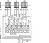
Try again and again, you'll have to click to enlarge it. I believe this is a parallel circuit between valves. Any thoughts. There are 110 volts to main valve. They are also connected to the Main Power board which is dc also. I am thinking that there is power in line 1 from Main power board then it looks like line 2 are all connected together. There is DC voltage and AC voltage in this complete circuit, which I am not to familiar with. DC and AC circuits, and with a digital readout and digital brain makes it a little confusing. Can images be deleted, after I post an image and get clarification I will delete them to save space. Thanks.https://www.electro-tech-online.com/attachments/valves-png.55424/
 

Attachments

  • valves.PNG
    valves.PNG
    83 KB · Views: 158
Last edited:
What is the problem?
 
No problem. Just wondering if it is a parallel or series circuit. I am thinking it is parallel circuit. I am studying different circuit designs and just trying to figure them out. I know a simple circuit, but the more complex ones are a bit harder. Of course this may be simple to you. I could go into many ideas about the circuit, but it would probably be not worthwhile and to time consuming.
 
No problem. Just wondering if it is a parallel or series circuit.

It's one or the other, or neither. I tend to choose neither.

Apparently one terminal (2) of all valves are all tied together. However, this neither makes it a parallel nor a series circuit. It all depends on other connections not shown here.

What is this--a washing machine? My guess is that each valve is wired independently to the timer. If two valves are energized at the same time, I guess you could say they're in parallel.
 
I am thinking that all the valves are parallel, because though all the valves run off one central valve with solenoids opening and closing them. I figure it would take 110 volts for each valve to open. I have the whole schematic, I could upload it. I'm not to familiar with these micro controlled circuits, but I would like to learn how to read the schematics for them. Let me know if your interested and I could upload the whole schematic. Then I could delete it later. Thanks.
 
Try to post better images. That one is practically unreadable (too small and fuzzy).

I dont know what your PC monitor is showing, but I see a clear png image, which is big enough and easy to read.??
 
I dont know what your PC monitor is showing, but I see a clear png image, which is big enough and easy to read.??
Note that OP has changed his first post AFTER carbonzit reply.
 
Note that OP has changed his first post AFTER carbonzit reply.

Many thanks, the OP didn't say in his EDIT he had changed the image.
 
Last edited:
I am thinking that all the valves are parallel, because though all the valves run off one central valve with solenoids opening and closing them. I figure it would take 110 volts for each valve to open. I have the whole schematic, I could upload it. I'm not to familiar with these micro controlled circuits, but I would like to learn how to read the schematics for them. Let me know if your interested and I could upload the whole schematic. Then I could delete it later. Thanks.

I'm curious: why are you concerned about whether it's a parallel or serial circuit?

As I said earlier, it really is neither. Each valve has some kind of switch (mechanical or electronic) that controls it, so they're all wired independently of each other, so they're not really in parallel. Technically, if two valves are on, they're in parallel, as they have a common power source. But what does it matter?
 
Yes Sir! I changed the image to a bigger clearer one. I think it is parallel, but I suppose if the power at the main valve was 110 volts then I suppose the rest could be series. But it looks to me like the #2 terminal all hooked together with the #1's terminals hooked to power from the main power board, which is micro controlled. That is why I am thinking each valve is wired in parallel. I may be wrong. But each valve has a separate solenoid I am 99% sure. Of course that doesn't mean there in series with the main valve, or parallel.
 
Status
Not open for further replies.

Latest threads

New Articles From Microcontroller Tips

Back
Top