Continue to Site

Welcome to our site!

Electro Tech is an online community (with over 170,000 members) who enjoy talking about and building electronic circuits, projects and gadgets. To participate you need to register. Registration is free. Click here to register now.

  • Welcome to our site! Electro Tech is an online community (with over 170,000 members) who enjoy talking about and building electronic circuits, projects and gadgets. To participate you need to register. Registration is free. Click here to register now.

IR Sensor..................

Status
Not open for further replies.

chamilackjm

New Member
Once break ir beam, how can i keep led light continue on and manually and automatically off......... anyone can get the update circuit..... i want to update receiver circuit.........

following link you can see the all details about this circuit................

**broken link removed**

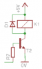
in receiver circuit some places can't understand......
 
If you Google latch you will find a way to "save" the light break. So you can feed the output of your receiver to the latch and reset the latch with your manual or automatic pulse.
 
The PNP transistor in the transmitter is drawn upside-down. The collector should connect to the IR LED, not the emitter.
The receiver circuit should work fine.
What don't you understand?
 
The PNP transistor in the transmitter is drawn upside-down. The collector should connect to the IR LED, not the emitter.
The receiver circuit should work fine.
What don't you understand?

longrangeirbeamcutdetector_1292248033.png

what had done that i rounded place? i was think , it is connect to the ic2 power supply isn't it?.....
ic 2 have not both 8 and 16 pin, how can i mark this likewise that picture... i use the eagle software... please explain that...
 
Last edited:
chamilackjm,

Look at the CD4017, the Q9 bit is tied to the enable
pin. The enable pin stops all counting and holds the
current state. This keeps the Q9 pin high until the
IR beam is unblocked and resets the 4017.

As ronv says look at a latch if you want to maintain the
beam broken state and reset it manually.

jerryd

thanks..... so i use the switch for q9 can i do it???
 
Last edited:
I don't think the relay in the receiver will work because the emitter-follower transistor T2 has too much voltage loss:
1) The output high of the CD4017 with a 5V supply and a current of 0.2mA into R7 is 4.8V.
2) The voltage lost across R7 with a current of 0.2mA is 2.0V.
3) Therefore the base voltage of T2 is only 2.8V.
4) Therefore the emitter voltage of T2 and the voltage at the relay coil is only 2.15V.
5) The transistor has a base current of only 0.2mA so the relay coil current will be about only 4mA.

T2 should be a common-emitter type so that it can drive the relay coil with nearly 5V.
 
The transistor and relay coil should be connected like this:
 

Attachments

  • transistor and relay.PNG
    transistor and relay.PNG
    5.1 KB · Views: 192
chamilackjm,

Audioguru says "The PNP transistor in the transmitter is
drawn upside-down". I questioned the orientation of this
transistor when I wired up the circuit. Seems like the
emitter should be the other way around in order to forward
bias the diode.

I tried it both ways and the signal going to the diode was
exactly the same and the IR reciever didn't care either.

Maybe the transistor is in Saturation Mode one way and Forward
Active Mode the other way. I'm not sure, maybe audiogugu can
wade in on this.

As to the output of the reciever it's exactly the same as the
32HZ signal out of pin 5 of the 556. I took a scope picture
but my camera battery died so I can't attach it.

I didn't try the relay circuit because I just put a speaker,
driven by a transistor on the output of the 4017.

jerryd
 
chamilackjm,

Audioguru says "The PNP transistor in the transmitter is
drawn upside-down". I questioned the orientation of this
transistor when I wired up the circuit. Seems like the
emitter should be the other way around in order to forward
bias the diode.

I tried it both ways and the signal going to the diode was
exactly the same and the IR reciever didn't care either.

Maybe the transistor is in Saturation Mode one way and Forward
Active Mode the other way. I'm not sure, maybe audiogugu can
wade in on this.
The transistor has a base current of about 4.2mA and if it was connected properly would have a collector current through the LED of about 11.8mA. Then its current gain needs to be only 2.8 so it works the same when it is connected backwards.
 
Status
Not open for further replies.

Latest threads

New Articles From Microcontroller Tips

Back
Top