Electro Tech is an online community (with over 170,000 members) who enjoy talking about and building electronic circuits, projects and gadgets. To participate you need to register. Registration is free. Click here to register now.
Welcome to our site! Electro Tech is an online community (with over 170,000 members) who enjoy talking about and building electronic circuits, projects and gadgets. To participate you need to register. Registration is free. Click here to register now.
I don't think so. Do you have some reason to suspect instability? A root locus diagram would answer the question difinitively. You might also try the Routh-Hurwitz criteria.
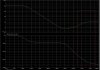
Too close for comfort IMO. You've got gain >1 and phase ~ -180 just shy of 100MHz. 5% tolereance here, 2% tolereance there, could blow up. Need bigger phase margin anwhere where gain >1 (0dB).
As for the red box, I dunno. Does the system really have that much bandwidth?
Too close for comfort IMO. You've got gain >1 and phase ~ -180 just shy of 100MHz. 5% tolereance here, 2% tolereance there, could blow up. Need bigger phase margin anwhere where gain >1 (0dB).
As for the red box, I dunno. Does the system really have that much bandwidth?
I don't think so. Do you have some reason to suspect instability? A root locus diagram would answer the question difinitively. You might also try the Routh-Hurwitz criteria.
Can pspice make a root lucus diagram out of a circuit simulation?
The reason why i suspect unstablity is because of the the gain plot recrosses above the 0db point while the phase is much greater than the 180 degrees point. That the section I have outlined in red.
As far as stablity goes, as far as I understand, if you apply an ideal step reponse with a feedback loop, you are essetically inputing a frequency of infinity, therefore if your system is unstable at any frenquency (even if its at 100Ghz) it will show.
Probably not. Still 80 dB is 10 Volts from a millivolt input. You'll reach sturation long before sability becomes an issue. I would suspect that there is something wrong with the thing you are simulating. What is it by the way.
As far as stablity goes, as far as I understand, if you apply an ideal step reponse with a feedback loop, you are essetically inputing a frequency of infinity, therefore if your system is unstable at any frenquency (even if its at 100Ghz) it will show.
What you say about the step function is true, but real components cannot respond to a step input in an ideal fashion. Real components have slewrate limitations and will saturate when the gain is large like 80 dB.
The whole purpose of feedback is to trade gain for bandwidth. I think there is something wrong with the simulation. What is it you are trying to simulate?
Probably not. Still 80 dB is 10 Volts from a millivolt input. You'll reach sturation long before sability becomes an issue. I would suspect that there is something wrong with the thing you are simulating. What is it by the way.
Two stage opamp with a series cap and resistor in the second stage feeding back from output to the input (miller cap).
I dont think there is anything wrong with my simulations because I dont have any ideal parts in my circuit besides an idea current source and voltage source.
How can you not AC couple the inputs? A millivolt of DC offset will peg the output with that much gain at DC. There is something wrong with this picture, but I'm no expert at IC design and those little parameters are meaningless to me. Perhaps the feedback impedance is large enough to effectively remove it from consideration.
Wee, it has 20dB of gain with -300 degrees of phase shift, but it's an open loop circuit, so it shouldn't be unstable. Apply feedback and we have another ball game.
It was alleged that the R and the C on the output stage constitute something that would give a different picture. The problem is in the high impedance differential stage. Stability ceases to be an issue when the output goes to the rail which any open loop system will do with the slightest provocation. I don't really know what to say except that the notion of testing an open loop system for stability seems - well...quaint. But I'm just an old fashioned greasy-thumb engineer.
If you think about the root locus of an ideal open loop gain stage, with no poles and no zeros you begin to get the idea that stability is kind of a meaningless concept. It doesen't oscillate, it doesn't limit cycle, and its output does not grow with out bound. It just goes to the rail and stays there, happy as a clam.
This site uses cookies to help personalise content, tailor your experience and to keep you logged in if you register.
By continuing to use this site, you are consenting to our use of cookies.