Well I'm a bit ahead of myself here as replacing the BS250 didn't quite seem to work on my Junebug.. but I've got some LF parts to program up and I fancy getting the circuit done.
I have an ICD connection to pin header for use in a breadboard. I left room between the connections to fit the diodes and 3.3v regulator (hence my capacitor thread earlier).
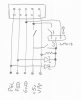
Is it a bad idea to build a circuit as shown in the attachment? I plan on using jumpers, completely removing the LM1117 from the circuit and connecting the +5v straight through normally. I haven't drawn the capacitors in, I'll fit them after.
The advantage is that it can be built in a very small space on stripboard and it's not too difficult to swap jumpers.
I have an ICD connection to pin header for use in a breadboard. I left room between the connections to fit the diodes and 3.3v regulator (hence my capacitor thread earlier).
Is it a bad idea to build a circuit as shown in the attachment? I plan on using jumpers, completely removing the LM1117 from the circuit and connecting the +5v straight through normally. I haven't drawn the capacitors in, I'll fit them after.
The advantage is that it can be built in a very small space on stripboard and it's not too difficult to swap jumpers.