Continue to Site

Welcome to our site!

Electro Tech is an online community (with over 170,000 members) who enjoy talking about and building electronic circuits, projects and gadgets. To participate you need to register. Registration is free. Click here to register now.

  • Welcome to our site! Electro Tech is an online community (with over 170,000 members) who enjoy talking about and building electronic circuits, projects and gadgets. To participate you need to register. Registration is free. Click here to register now.

LED circuit, What is it?

Status
Not open for further replies.

dr.power

Member
Hello friends.

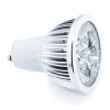
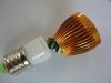
As Some of you may know I started a thread about LEDs, two or three days ago. When I was searching I noticed that the LED's which are used in home aplications and supplied by 110 or 220V use a circuit inside them, Can you guys plz let me know why that circuit is needed (except of lowering the mains voltage of the LED's). I took one a part and noticed that there is a chip and a coil/choke plus other components

Thanks.
 

Attachments

  • led-4w-downlight-gu10-edit-de_1.jpg
    led-4w-downlight-gu10-edit-de_1.jpg
    59.4 KB · Views: 173
  • 3W-1.jpg
    3W-1.jpg
    45.2 KB · Views: 173
Ronv, exactly... it's simply a SMPS... a switcher to deliver a set current into the LEDs, and the voltage will depend on what the LEDs drop for that current. A very efficient way to power LEDs because all the power goes to them, and you don't have dropping resistors.
 
Ronv, exactly... it's simply a SMPS... a switcher to deliver a set current into the LEDs, and the voltage will depend on what the LEDs drop for that current. A very efficient way to power LEDs because all the power goes to them, and you don't have dropping resistors.

Can you please explane your meaning to me? I serached but could not find any thing, Maybe I did not have enough clue to serach...

Why giving a set current into the LEDs? Why they do not try to adjust/set the Volatge instaed of current?

What will happen if we use a dropping resistor in series with the LED(s)?

Power is VxI so why try to set the current but not volatge here?

Any link please so that I could read it?

Thanks again
 
LEDs are a current device not like a light bulb.
They are made to work at some mA. They are not designed to work at a voltage.
LEDs are much like Zener diodes.
For hobby electronic, there is a big misunderstanding. A 3 volt LED should not be run at 3 volts. A full current it will have about 3v.
 
Maybe your electricity is 220VAC. An ordinary white LED operates at 20mA and has a forward voltage drop of about 3.2V.
The LED needs DC, not AC so you use a full-wave bridge rectifier and a filter capacitor (to prevent flickering).
The capacitor will have 309.7VDC.
If you use a series current-limiting resistor then its value is (309.7V - 3.2V)/20mA=) 15325 ohms and it will heat with (309.7V - 3.2V) x 20mA= 6.13W.
A huge 10W resistor will be VERY hot.

But if you use a switching LED driver circuit it will be small and will barely get warm.
 
LEDs are a current device not like a light bulb.
They are made to work at some mA. They are not designed to work at a voltage.
LEDs are much like Zener diodes.
For hobby electronic, there is a big misunderstanding. A 3 volt LED should not be run at 3 volts. A full current it will have about 3v.

Hi Ron,
Every electronics componenet is made to work at some mA, SAo plz can you clear yourmeaning if possible?
As I know in every electronic device you try to give it a specific voltage and it determines its current draw according to its resistance.
So for the LED you talked about, What will happen if you try to turn it on in say 2.5V? Most of the LEDs I ever seen are working just by a series resistor to decrease the volatge and they are satisfied at long term.
 
Why giving a set current into the LEDs? Why they do not try to adjust/set the Volatge instaed of current?

What will happen if we use a dropping resistor in series with the LED(s)?

Power is VxI so why try to set the current but not volatge here?

Any link please so that I could read it?

Thanks again

An LED is a rectifier (Light Emitting Diode), it drops a voltage when you put a current through it. They are rated to give a specific light output per current passing through. Normally, when you light an LED, you have a specific voltage you are driving it from, say 5V or 12V. You have to put a 'dropping' resistor in line with it to limit the current and drop the rest of the voltage. Resistance_value = Source_voltage - LED_voltage / LED_current. This is very inefficient, as most of your power is lost across the resistor. The switching power supply delivers a set current, whatever current your LED is spec'd at, and the voltage will be determined by the LED itself, so there is no other power lost in the circuit, except the regulator circuit, which is in the neighborhood of 95% efficient, as opposed to an Resistor Limited circuit, which would be about 40% (5V source), or 16% (12V into 1 LED) or 33% (12V into 2 LEDs in series).
 
Maybe your electricity is 220VAC. An ordinary white LED operates at 20mA and has a forward voltage drop of about 3.2V.
The LED needs DC, not AC so you use a full-wave bridge rectifier and a filter capacitor (to prevent flickering).
The capacitor will have 309.7VDC.
If you use a series current-limiting resistor then its value is (309.7V - 3.2V)/20mA=) 15325 ohms and it will heat with (309.7V - 3.2V) x 20mA= 6.13W.
A huge 10W resistor will be VERY hot.

But if you use a switching LED driver circuit it will be small and will barely get warm.

Thanks audioguru,

How the switching LED driver is able to causes so? Why not use an AC cap instead of the limiting resistor to decrease the mains voltage?
Are you saying that the driver is just a normall swiching power supply lik those that are used in some transformers and adaptors? If so why it is called a CURRENT driver or a Constant current driver?
 
An LED is a rectifier (Light Emitting Diode), it drops a voltage when you put a current through it. They are rated to give a specific light output per current passing through. Normally, when you light an LED, you have a specific voltage you are driving it from, say 5V or 12V. You have to put a 'dropping' resistor in line with it to limit the current and drop the rest of the voltage. Resistance_value = Source_voltage - LED_voltage / LED_current. This is very inefficient, as most of your power is lost across the resistor. The switching power supply delivers a set current, whatever current your LED is spec'd at, and the voltage will be determined by the LED itself, so there is no other power lost in the circuit, except the regulator circuit, which is in the neighborhood of 95% efficient, as opposed to an Resistor Limited circuit, which would be about 40% (5V source), or 16% (12V into 1 LED) or 33% (12V into 2 LEDs in series).

Thanks, But I have lighten a lot of LEDs by 220V Ac using an AC cap in seriess with the mains and a rectifier diode, I can even remember that I made a 2 channels flasher this way, And it worked very well for one year or so.
 
Hi Ron,
Every electronics componenet is made to work at some mA, SAo plz can you clear yourmeaning if possible?
As I know in every electronic device you try to give it a specific voltage and it determines its current draw according to its resistance.

That's where you're going wrong - your entire premise is incorrect - that only applies to a pure resistance.

So for the LED you talked about, What will happen if you try to turn it on in say 2.5V? Most of the LEDs I ever seen are working just by a series resistor to decrease the volatge and they are satisfied at long term.

Again, incorrect premise - the resistor is to limit the current, the fact it drops the voltage is a consequence of that limiting.

LED's are essentially similar to low voltage zener diodes (and are commonly used for that purpose) - so assuming you have a 6V supply, and the turn on voltage of the LED is 2.5V, you need to drop 3.5V across the resistor. The other figure you need is the current, so lets say 10mA, you can now work the resistance required out (3.5V/0.01A = 3500 ohms). If you now want the LED to be brighter, then increase the current - say 20mA, voltage is the same (as far as this example goes), so it's now 3.5V/0.02A = 1750 ohms.

The best way to run an LED is from a constant current source (less waste than a series resistor, and immune to voltage variations), which is why LED maps use constant current sources to power the LED/LED's.
 
Thanks audioguru,

How the switching LED driver is able to causes so? Why not use an AC cap instead of the limiting resistor to decrease the mains voltage?

Because it's pretty unsafe.

Are you saying that the driver is just a normall swiching power supply lik those that are used in some transformers and adaptors? If so why it is called a CURRENT driver or a Constant current driver?

No he's not saying that, he's saying it's a current source - they are VERY similar devices, it's mainly just a question of the feedback employed (a voltage regulator monitors the voltage, and a current regulator monitors the current).
 
Also, like a resistor, a capacitor will have an impedance at a specific frequency, and if you use it to decrease the mains it will lose power just like a resistor.

The better switching regulators limit BOTH current and voltage, and have feedback pins to do so. One set of feedback is to limit voltage. If you don't use it, it won't limit it. Same with current, you can put an inline resistor (2.5mohm, or .0025 ohms) to set the limit on the inductor current. Or, if there is no current limit function on the regulator itself, you can put the inline resistor in the ground return of the load and use the voltage limit feedback to limit the current.
 
Also, like a resistor, a capacitor will have an impedance at a specific frequency, and if you use it to decrease the mains it will lose power just like a resistor.

You won't actually lose power in a capacitor. Well, you will loose a tiny bit of power because capacitors aren't perfect, but you won't lose much.

There are various circuits that run LEDs from the mains, and limit the current with a capacitor. They are often called transformerless LED drivers. There is next to no heat generated in the capacitor.

The current in the capacitor is not in phase with the supply voltage, so nearly all of the energy absorbed by the capacitor from the mains in one part of the cycle goes back into the mains in another part of the cycle.
 
Why giving a set current into the LEDs? Why they do not try to adjust/set the Volatge instaed of current?
Because the V-I characteristic of a diode is very steep and heavily depends on temperature and varies a lot between different batches of the same led, meaning that a small variance in voltage will cause large variance in current, and current is ultimately what defines the brightness and what may kill the diode.
The consequence is that say on LED will draw 20mA at 2.5V, but another piece could draw 20mA at 2.4V, now put 2.5V across the second one and the current will rise steeply to say 40mA. Obviously this is not a good idea, so you allways want your source to put current through the diode and not set voltage across the diode.
 
Status
Not open for further replies.

Latest threads

New Articles From Microcontroller Tips

Back
Top