crashmeplease
New Member
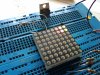
I have been designing and simulating an 8x8 Bi LED Matrix display, and have a few questions..
My original simulated model uses common cathode displays, 595 shift registers driving the columns, and 2803 darlington arrays doing the rows, all connected to an avr. Pretty much like many of the designs already out there tbh. And seemed to work quite well..
My problem is that I didn't realise at the time that my displays that I have are common anode, and I cant figure out the best way to hook these up. At the moment I am thinking I need a decent sized pnp transistor from the micro to drive an entire row instead, or can I somehow connect pull up resistors to the 2803 darlington array to give a positive output rather than to ground. I would really like to continue to drive the columns with the 595s.
I can add diagrams if this helps.
TIA")
My original simulated model uses common cathode displays, 595 shift registers driving the columns, and 2803 darlington arrays doing the rows, all connected to an avr. Pretty much like many of the designs already out there tbh. And seemed to work quite well..
My problem is that I didn't realise at the time that my displays that I have are common anode, and I cant figure out the best way to hook these up. At the moment I am thinking I need a decent sized pnp transistor from the micro to drive an entire row instead, or can I somehow connect pull up resistors to the 2803 darlington array to give a positive output rather than to ground. I would really like to continue to drive the columns with the 595s.
I can add diagrams if this helps.
TIA