Continue to Site

Welcome to our site!

Electro Tech is an online community (with over 170,000 members) who enjoy talking about and building electronic circuits, projects and gadgets. To participate you need to register. Registration is free. Click here to register now.

  • Welcome to our site! Electro Tech is an online community (with over 170,000 members) who enjoy talking about and building electronic circuits, projects and gadgets. To participate you need to register. Registration is free. Click here to register now.

LED Xmas Light repair help

Hafcanadian

New Member
I have one of the neighborhood’s more extensive Xmas light displays. Every year one or more sets or strings go haywire, and I try to find the issue. I have minimal electronics acumen, but have ferreted out and repaired a few issues in my day. My soldering skills have improved, and although an essential tremor too often confounds my efforts thereto, I by hook or by crook sometimes manage to get failed appliances, flashlights, automotive and RV devices, and even Xmas strings up and running.

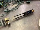
Over the years I’ve accumulated Xmas lights of different sorts, LED and incandescent, plain straight and net style, simple and “in motion” controlled. I have both a Light Keeper Pro and an LED Keeper light repair “guns”. They are relatively useless for module controlled sets, but do help detect failed lamps. It’s the module controlled sets that confound me.

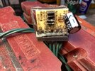
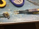
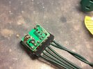
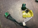
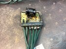
This year some rain water got into one LED net set and it blew both 3A fuses. I took the module apart and dried it, then cleaned up the detritus on the circuit board. One rusted tail of a capacitor broke off, and I resoldered it back in. I think this one runs two 35-lamp sides, 70 lamps total. I took apart the last lamp before the female outlet end plug because it was badly corroded and one LED tail had broken off. I cleaned it, DeoxITed both blades, and put a new lamp in the socket.

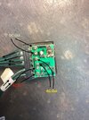
It still blows both fuses immediately when plugged in. I’m relatively ignorant on how these things work, so please forgive that. When I put + and - meter probes in the female end plug, I get continuity. Shouldn’t there be no connection between the two, and is this indicative of the short circuit? I can’t see evidence of a short in the board’s connections, but there has to be one somewhere. Is it possibly in a board component - there’s only 4 resistors and a capacitor. There’s no obvious wire damage within the net that would cross short, and there are two sides each of 35 lamps, so I’d expect an in-side short to blow only one fuse, not both.

Any offered clarity to my understanding of how these work would be appreciated.

Joel
0_IMG_0170.jpeg
0_IMG_0172.jpeg
0_IMG_0174.jpeg
0_IMG_0176.jpeg
1_IMG_0178.jpeg
 
Those are diodes, not resistors.

The four diodes form a full bridge rectifier which changes the AC to DC, and the capacitor smoothes the DC.

Line and Neutral should connect through from the male to the female connectors, but there should not be continuity between Line and Neutral.

When testing a diode, a meter should show continuity when connected one way but not the other.

Each leg of the capacitor is connected to two diodes. The gap between those two connections is very small and looks to be quite dirty. You should clean that up first. If it works, seal it up against water getting in again.
 
1740171837671.png


Ensure > 1mm gap. ( very poor design that should have an air slot for high voltage)
After PCB repairs, the surface must be protected from future moisture. & contamination.
Use Nail Polish brushed over exposed solder.
 
Last edited:
Thanks for replying. My bad for the diode/resistor thing. I’ve read enough and dealt with both enough to know better, but at 76 and a few medical maladies, I too easily forget what I’ve tried to learn.

First thing, I will disconnect the four wires going to the set, and see if the fuses still blow. Whether they do or not I’ll resolder the pads that are now poorly done, although my tremor usually makes iron control on small spots difficult - which is why a couple of them now look sloppy. In the process I’ll enlarge the gap alluded to, though I test no continuity between the two pads.

At one time I knew what the symbols you diagrammed meant, but a few now escape my memory, so I have incentive to dig out my books and refresh my stagnant electronics acumen. ;)
 

Attachments

  • 0_IMG_0181.jpeg
    0_IMG_0181.jpeg
    312.2 KB · Views: 41
It may not be reliable to test them while they are still connected to the circuit. If there is a short, it will show some diodes as faulty.

I suggest that you disconnect one end of each diode that tests as faulty and test again.
 
Thank you, will do. I think the replacement is IN4007. The two bad ones had no end stripe or characters; could’ve burned off I suppose.
 

Attachments

  • 0_IMG_0186.jpeg
    0_IMG_0186.jpeg
    327.6 KB · Views: 25
4 new diodes in. Board cleaned up better. Fuses don’t blow. But the LED’s still don’t light up. 119V at the first 2 wires on the board from the plug, and at the other end of the set in the female plug.

One issue was that some of the copper track around the pin holes at the capacitor end for the two middle diodes is worn away. Soldering there meant the solder flowed to the adjoining pins more, and I had a time of it trying to coax solder to completely envelope one or two of the diode pins. So they aren’t totally independent, and look sloppier than the 4 pins at the other end, but do share common trace with each other anyway.
 

Attachments

  • 1_IMG_0191.jpeg
    1_IMG_0191.jpeg
    162.4 KB · Views: 37
  • 0_IMG_0189.jpeg
    0_IMG_0189.jpeg
    133.6 KB · Views: 31
  • 1_IMG_0178.jpeg
    1_IMG_0178.jpeg
    237.2 KB · Views: 31
  • 0_IMG_0176.jpeg
    0_IMG_0176.jpeg
    372.5 KB · Views: 30
Last edited:
I redid the “blended” solder points after removing, testing, and reinstalling the capacitor (9+ uf). Soldering the three proximal diode/cap points (cap negative end) was difficult because of trace damage that limited solder flow surrounding the two diode pins. After cleaning flux debris all seemed okay, but the lamps still wouldn’t light up.

Going through 70 LED’s one at a time checking with the Lightkeeper I’ve done too much of already. Some lamps “blink”, some are solid, but most are inconsistent… if the LEDs’ two wires don’t contact the Lightkeeper’s test port just so (and yes, I get + and - oriented correctly), they don’t light up one second but kinda-sorta the next, or flicker once, then nothing. Frustrating trying to do that over a full 70 set, often removing the lamp from its holder to insure tester contact. But that wire straightening/rebending oft results in a broken wire.

My LCR tweezer has an LED ability to its diode test feature. But these lamps that flash/flicker apparently have a Type 1-like, built-in breaker/bimetal strip, and the tweezers alternate between stats reporting and “damage”, which confused me at first, and perhaps still. Because apparently some lamps are not meant to flash and some are, testing seemed a long job. On top of it a lamp may test okay but a slightly poor socket contact be a culprit that fools me.

Last night I was checking the DC Out wires for voltage numbers and my tremor resulted in a clumsy short across them, blowing fuses again. Aggravated with all the time spent, and given I could buy a new one likely for a lot less than the value of my time investment heretofore, I tossed the whole works in the garbage. Today I question that waste if instead I invest a bit more and eventually resolve it, and include the return on investment of the learning experience. So if other projects’ time allows, I may retrieve the set, replace fuses again, and start through the lamps again. Any that continuously read “damage” on my LCR tweezers get replaced with a standard new 3.4v of appropriate color.

Any helpful input re. the variable lamp function and my greenhorn test procedures would be appreciated.
 
Last edited:
been there done that a few times, but not any more
 
I redid the “blended” solder points after removing, testing, and reinstalling the capacitor (9+ uf). Soldering the three proximal diode/cap points (cap negative end) was difficult because of trace damage that limited solder flow surrounding the two diode pins. After cleaning flux debris all seemed okay, but the lamps still wouldn’t light up.

Going through 70 LED’s one at a time checking with the Lightkeeper I’ve done too much of already. Some lamps “blink”, some are solid, but most are inconsistent… if the LEDs’ two wires don’t contact the Lightkeeper’s test port just so (and yes, I get + and - oriented correctly), they don’t light up one second but kinda-sorta the next, or flicker once, then nothing. Frustrating trying to do that over a full 70 set, often removing the lamp from its holder to insure tester contact. But that wire straightening/rebending oft results in a broken wire.

My LCR tweezer has an LED ability to its diode test feature. But these lamps that flash/flicker apparently have a Type 1-like, built-in breaker/bimetal strip, and the tweezers alternate between stats reporting and “damage”, which confused me at first, and perhaps still. Because apparently some lamps are not meant to flash and some are, testing seemed a long job. On top of it a lamp may test okay but a slightly poor socket contact be a culprit that fools me.

Last night I was checking the DC Out wires for voltage numbers and my tremor resulted in a clumsy short across them, blowing fuses again. Aggravated with all the time spent, and given I could buy a new one likely for a lot less than the value of my time investment heretofore, I tossed the whole works in the garbage. Today I question that waste if instead I invest a bit more and eventually resolve it, and include the return on investment of the learning experience. So if other projects’ time allows, I may retrieve the set, replace fuses again, and start through the lamps again. Any that continuously read “damage” on my LCR tweezers get replaced with a standard new 3.4v of appropriate color.

Any helpful input re. the variable lamp function and my greenhorn test procedures would be appreciated.
As you said, I'd do it for the learning experience but not a water damaged set.

Physicians like to be "groupers" and come up with a diagnosis that addresses all symptoms. This process breaks down when a patient is very reluctant to come in and they have multiple maladies. Giving up on the idea that only one malady is causing the group of symptoms feels like a a failure. And once you allow yourself to address the symptoms with two or more diagnoses, the chance of picking the wrong two goes way up.

This is the case for water damaged electronics. It is likely damaged to the point of malfunction and then left out in the elements for some additional time before being rescued. Then the attempts to fix the problem by powering it up and desoldering can create even more problems. It is well worth throwing in the bin.
 

Latest threads

New Articles From Microcontroller Tips

Back
Top