Gayan Soyza
Active Member
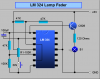
Here is a lamp fader designed in LM 324.There are many op amp designs used to fade LED's.You may have experienced like this before.In the original circuit the R1 is directly connecting to pin7 (not via SW).
It starting from zero.The brightness is increasing smoothly & after it reaches to maximum brightness again its reducing to zero.
I added a SW near the R1 so when you press SW its changing the brightness level from zero to max & max to zero.
My ques is I need two switches one is to increase brightness other is to decrease.
Can anybody suggest a method for this without taking a microcontroller.
I have attached the Schematic.
Thankx.