Electro Tech is an online community (with over 170,000 members) who enjoy talking about and building electronic circuits, projects and gadgets. To participate you need to register. Registration is free. Click here to register now.
Welcome to our site! Electro Tech is an online community (with over 170,000 members) who enjoy talking about and building electronic circuits, projects and gadgets. To participate you need to register. Registration is free. Click here to register now.
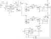
dch222 thanks for the info, but I have the data sheet and the box for the LM 324 has the pin out .
The schematic does not have the pins numberd for the LM 324. I am new to electronics and was wondering if I just missing somthing in the schematic.
Thanks ,sam
dch222 thanks for the info, but I have the data sheet and the box for the LM 324 has the pin out .
The schematic does not have the pins numberd for the LM 324. I am new to electronics and was wondering if I just missing somthing in the schematic.
Thanks ,sam
In other schematics I have seen that show the LM324, break it down into 4 separate triangular symbols, and then list the input/output numbers on each triangle (1-14).The schematics in the article dont show any of those numbers.
Is this a mistake or is there somthing I am missing( like my brain)?
Thanks, sam
Edit: Or does it only matter that I keep the inputs and output together for each op amp? Like 1 together , 2 together.....3,4.
This site uses cookies to help personalise content, tailor your experience and to keep you logged in if you register.
By continuing to use this site, you are consenting to our use of cookies.

")