Electro Tech is an online community (with over 170,000 members) who enjoy talking about and building electronic circuits, projects and gadgets. To participate you need to register. Registration is free. Click here to register now.
Welcome to our site! Electro Tech is an online community (with over 170,000 members) who enjoy talking about and building electronic circuits, projects and gadgets. To participate you need to register. Registration is free. Click here to register now.
The oscilator has many frequencies, for my circuit about 3 freqs. how to determine the main frequency of oscilator to calculate inductor ?? pls help !!!
Example, I made this circuit and used the radio pocket to receive transmitted signal. the main frequency i expected was 94Mhz. but i am not sure that's center frequency becauze of having many frequencies such as 88Mhz and 104Mhz. ???
thank for ur answer.. the above circuit i made many years ago . it really was bad for quality. But the knowledges i studies from the phenomenon occur within the circuit are very useful. do you explain the operation principle of the circuit?
While that "transmitter" circuit is just a piece of nasty, I suspect that the output is at some frequency around 100Mhz (ish) with significant harmonic content, ie signals at 200, 300 400, 500 etc Mhz.
I suggest that the reason you are receiving this thing at several frequencies with your receiver is due more to the poor performance of the receiver than the transmitter.
The receiver will almost certainly have many "spurious" responses.
oh . my FM poket operate in the banwidth from 72 to 108MHz and have good performance. It really receved there frequencies 88Mhz ,94 and 104 Mhz. ofcause , the circuit i made have some different from in the pic.
You can use it without worrying too much. I have built and used several of these over the years.
Just fiddle with the inductor until you can tune it in or your receiver. To test to make sure you did not tune in an image of the frequency, place your finger near the inductor. The frequency should drop a little bit. If the frequency rises, then you are looking at an image and the real signal is probably 25.4 MHz away from the image (2 x 10.7 MHz).
The frequency should drop a little bit. If the frequency rises, then you are looking at an image and the real signal is probably 25.4 MHz away from the image (2 x 10.7 MHz).
thank for ur answer.. the above circuit i made many years ago . it really was bad for quality. But the knowledges i studies from the phenomenon occur within the circuit are very useful. do you explain the operation principle of the circuit?
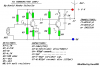
T1 is just a common emitter amplifier which boosts the signal from the microphone.
T2 is the RF oscillator.
Oscillator wise, it's actually configured as a common base amplifier. At DC it's base is biased by T1's collector. At AC C4 connects T2's base to +V which as far as AC is concerned is the same as 0V. L1 and C6 form a tuned circuit and C5 provides some positive feedback to T2's emitter which serves as the input. The circuit behaves like an oscillator because of positive feedback, like when you hold the mic of connected to near to a speaker via an amplifier it oscillates at an audible frequency, creating a howling sound. In this case the circuit resonates at the frequency determined by the LC tuned circuit which should be in the FM band.
The circuit actually produces both AM and FM. The amplitude of the output signal will change as T2's base voltage is changed which alters its base and collector current and therefore its gain. The frequency is changed because the capacitance of TR2 is voltage dependant which changes the frequency of the tuned circuit.
My FM transmitter project severely overloads my cheap Sony Walkman radio and cheap clock radio so that it appears all over the dials. My high quality home stereo and car radio are not overloaded.
When I switch on the antenna attenuator that is labelled "local-distant" then the Sony radio is not overloaded when it is 20m and more away.
Its not that it actually overloads the IF; if the receiver is a single conversion superhetrodyne, then two different frequencies can beat with the local oscillator to create the IF (intermediate frequency). The most common IF is 10.7 MHz, so one frequency 10.7 above the local oscillator frequency and another frequency 10.7 MHz below the local oscillator frequency will both produce an output centered at 10.7 MHz. The tuning of the first stage is supposed to suppress the unwanted frequency.
(Remembered this in the shower) Also, I have noted that in cheap FM receivers with digital synthesizers, for reasons that are not entirely clear, a clean oscillator at a single frequency frequency will show up on several spots on the dial. This might be the result of the receiver being all on one chip and the reference for the synthesizer and its harmonics get into the wrong places on the chip. Its best to not use cheap digital tuning receivers that have digital tuning while turning in your transmitter.
T1 is just a common emitter amplifier which boosts the signal from the microphone.
T2 is the RF oscillator.
Oscillator wise, it's actually configured as a common base amplifier. At DC it's base is biased by T1's collector. At AC C4 connects T2's base to +V which as far as AC is concerned is the same as 0V. L1 and C6 form a tuned circuit and C5 provides some positive feedback to T2's emitter which serves as the input. The circuit behaves like an oscillator because of positive feedback, like when you hold the mic of connected to near to a speaker via an amplifier it oscillates at an audible frequency, creating a howling sound. In this case the circuit resonates at the frequency determined by the LC tuned circuit which should be in the FM band.
The circuit actually produces both AM and FM. The amplitude of the output signal will change as T2's base voltage is changed which alters its base and collector current and therefore its gain. The frequency is changed because the capacitance of TR2 is voltage dependant which changes the frequency of the tuned circuit.
Its not that it actually overloads the IF; if the receiver is a single conversion superhetrodyne, then two different frequencies can beat with the local oscillator to create the IF (intermediate frequency). The most common IF is 10.7 MHz, so one frequency 10.7 above the local oscillator frequency and another frequency 10.7 MHz below the local oscillator frequency will both produce an output centered at 10.7 MHz. The tuning of the first stage is supposed to suppress the unwanted frequency.
(Remembered this in the shower) Also, I have noted that in cheap FM receivers with digital synthesizers, for reasons that are not entirely clear, a clean oscillator at a single frequency frequency will show up on several spots on the dial. This might be the result of the receiver being all on one chip and the reference for the synthesizer and its harmonics get into the wrong places on the chip. Its best to not use cheap digital tuning receivers that have digital tuning while turning in your transmitter.
As already explained, the circuit produces both AM and FM modulation, no need for a varicap, it relies on changes in capacitnace inside the transistor.
As already explained, the circuit produces both AM and FM modulation, no need for a varicap, it relies on changes in capacitnace inside the transistor.
You are wrong, and the circuit won't work - the one on the mike is just to help prevent RF entering that way (so not too critical) the one on the base of the oscillator is absolutely essential, it's that component that makes it a common base circuit.
You are wrong, and the circuit won't work - the one on the mike is just to help prevent RF entering that way (so not too critical) the one on the base of the oscillator is absolutely essential, it's that component that makes it a common base circuit.
Yes, you're right, the capacitor across the mic. isn't too critical but the one on the base essential because it makes it common base which I already knew but forgot when I drew the schematic.
It was a silly idea, if you want to remove the AM, a varactor diode should be used.
if you want only the right frequency, its the frequency with peak power, so move your receiver and check the distance, the long range frequency of transmission is the center frequency.
This circuit and all other battery powered circuits need a supply bypass capacitor. Maybe a 0.002uF ceramic disc for RF and a 100uF electrolytic for audio.
FM radios ignore AM so the small amount of AM in these transmitters doesn't matter. If the radio is a super-regen the the AM will be demodulated.
This site uses cookies to help personalise content, tailor your experience and to keep you logged in if you register.
By continuing to use this site, you are consenting to our use of cookies.