Continue to Site

Welcome to our site!

Electro Tech is an online community (with over 170,000 members) who enjoy talking about and building electronic circuits, projects and gadgets. To participate you need to register. Registration is free. Click here to register now.

  • Welcome to our site! Electro Tech is an online community (with over 170,000 members) who enjoy talking about and building electronic circuits, projects and gadgets. To participate you need to register. Registration is free. Click here to register now.

Making an Avometer "multimeter" (AC & DC) with some filters

Status
Not open for further replies.
Salam alaikum (peace upon you)
Could I have any help in that project?

Build a digital Multimeter using Arduino.
• The device should be able to measure the following:
1. Voltage range [ -9 V, 9 V ].
2. Current Range [ -0.5 A – 0.5 A].
3. Resistance Range [ 50 Ω – 100 kΩ].
4. Can detect voltage and current frequencies up to 500 Hz only “Greater frequencies should be attenuated by 3rd order filter”.

Device sensitivity in each measurement mode should be calculated.

Even more;

Resistance range [10 Ω – 100 MΩ].
• Connectivity Test Feature.
• Measure the frequency of the input voltage and current signal.

Mainly, I have two problems
1) how to do the idea?
2) the circuit collapse after connecting
 
Last edited:
1) Accuracy of measurements desired ?
2) Resolution of measurements, V and I
3) Peak, Average, or RMS of AC inputs ?
4) Desired display to be used ?
5) Input Z of meter desired ?
6) Is this a school or class project for a course ?

Regards, Dana.
 
1) Accuracy of measurements desired ?
By calculate the difference between the simulation on spice model and the output values from the real circuit

2) Resolution of measurements, V and I?
I don't know , but could be 0.1 or 0. 01
(any reasonable value)
3) Peak, Average, or RMS of AC inputs ?
Could you suggest a AC input method, until now I don't know

4) Desired display to be used ?
16* 2 LCD

5) Input Z of meter desired ?
Expaine that point please

6) Is this a school or class project for a course ?
Project

** picture for the suggested circuit on spice program
 

Attachments

  • Screenshot_20210610_202456.jpg
    Screenshot_20210610_202456.jpg
    119.2 KB · Views: 394
Really, thanks a lot for that nick link, it's very helpful, I will try it.

I found for the ohm meter that nice link, also from the same website

Could you recommend an arduino Autoranging AC - DC ammeter?
I found some ideas, but not in my scope : like using sensor or make complex circuits or no give negative current value (only measures positive value, and I need negative value also)

Do you know any helpful link about making number (4) in requirements?
 
Last edited:
#4) I like the blue mode 16 x 2 or 4, 20 x 2 or 4. They are great displays
readability wise in daylight. Ebay, Banggood sell them. You can get
buss versions (4 or 8 bit) or I2C versions, and google driver for Arduino
several driver libraries available. Or use OLED, 4 color.....

Current -


Regards, Dana.
 
Thanks a lot, but I mean by number (4) that point
: Can detect voltage and current frequencies up to 500 Hz only “Greater frequencies should be attenuated by 3rd order filter”.


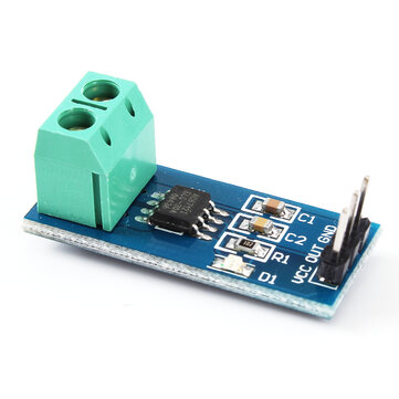
* for the current sensor, I want to the circuit myself, not pay a sensor. The circuit which I make should measure -ve and +ve in range [ -0.5 A – 0.5 A].
 
Status
Not open for further replies.

Latest threads

Back
Top