Hello,
I am tiring to get a voltage and current logger for my power supply, which has a positive and negative output. I am guessing the easiest way to do this is using an ADC and a PIC to a PC.
I have the following questions that I can’t seem to find answers for;
1. The power supplies output is 1-30VDC. Measuring the voltage is easy. I just used a resister divider to scale the voltage and measured it with an ADC. When I am measuring current, I will use a shunt (.1 10w resister). I will then use an op-amp to make the output single ended to feed to the ADC. If the voltage is 30v from the power supply, will I need to put it thought a resister divider before I feed it to the op-amp? From what I have read, the max voltage on the op-amp input (TL081) must be lower than the op amp supply voltage (15v). Is this correct, or can I just put the current sense resister straight onto the op-amp?
2. On the negative rail, I am thinking of just using an op-amp to invert the voltage for the ADC for voltage measurement. Is this an OK way of going about it?
3. Measuring the current on the negative rail has got me completely stumped. Should I first invert the voltage across the current shunt, and then use another op-amp to provide a single ended output for the ADC? Is there any other\better ways of doing it?
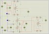
I have included a diagram of the current measuring circuits. The LEDs are just there to provide load for testing.
I don’t need any crazy accuracy from the measurements (.01 volts and 1 mA will done fine). I also don’t want to spend big $$ on in-amps and IC if I can get away with it.
Thanks for the help.
Mark
I am tiring to get a voltage and current logger for my power supply, which has a positive and negative output. I am guessing the easiest way to do this is using an ADC and a PIC to a PC.
I have the following questions that I can’t seem to find answers for;
1. The power supplies output is 1-30VDC. Measuring the voltage is easy. I just used a resister divider to scale the voltage and measured it with an ADC. When I am measuring current, I will use a shunt (.1 10w resister). I will then use an op-amp to make the output single ended to feed to the ADC. If the voltage is 30v from the power supply, will I need to put it thought a resister divider before I feed it to the op-amp? From what I have read, the max voltage on the op-amp input (TL081) must be lower than the op amp supply voltage (15v). Is this correct, or can I just put the current sense resister straight onto the op-amp?
2. On the negative rail, I am thinking of just using an op-amp to invert the voltage for the ADC for voltage measurement. Is this an OK way of going about it?
3. Measuring the current on the negative rail has got me completely stumped. Should I first invert the voltage across the current shunt, and then use another op-amp to provide a single ended output for the ADC? Is there any other\better ways of doing it?
I have included a diagram of the current measuring circuits. The LEDs are just there to provide load for testing.
I don’t need any crazy accuracy from the measurements (.01 volts and 1 mA will done fine). I also don’t want to spend big $$ on in-amps and IC if I can get away with it.
Thanks for the help.
Mark