Electro Tech is an online community (with over 170,000 members) who enjoy talking about and building electronic circuits, projects and gadgets. To participate you need to register. Registration is free. Click here to register now.
Welcome to our site! Electro Tech is an online community (with over 170,000 members) who enjoy talking about and building electronic circuits, projects and gadgets. To participate you need to register. Registration is free. Click here to register now.
i bymistakely etched pcb with a mirror image of layout.so ic ne555 which m using cannot be connected with pins at proper places.is there any other option except making it all again?
Mount the 555 on the other side of the board, soldering might be a challenge...if that does not work you could "dead bug" the chip (glue it down to the board upside-down and connect short jumpers off its leads)
What type of image did you try to upload? When you go to the "Manage Attachments" window it will show the type of files you can upload and their maximum allowable size.
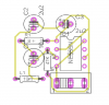
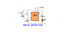
i got this schematic from internet.i am making it all again.can u just tell me its working?i know that when a metal or magnet is brought near inductor its frequency changes but is it a tank circuit and what 555 does?
i got this schematic from internet.i am making it all again.can u just tell me its working?i know that when a metal or magnet is brought near inductor its frequency changes but is it a tank circuit and what 555 does?
hi,
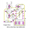
IF this is the copper side of the pcb, mount the 555 on this side and top solder the 555 pins.
The other components can be placed on the other side of the pcb.
The circuit produces a 'tone' in the speaker which will vary a little in frequency as a metal object is brought near to the 10mH inductor.
The 555 is configured as an Astable, it produces a square wave output which drives the speaker via the 10uF cap.
The frequency of the square wave is dependent upon C2, C3 and the 10mH, so as the inductance of the 10mH changes due to a close metal object, so does the sound you hear.
The 555 is configured as an Astable, it produces a square wave output which drives the speaker via the 10uF cap.
The frequency of the square wave is dependent upon C2, C3 and the 10mH, so as the inductance of the 10mH changes due to a close metal object, so does the sound you hear.
This site uses cookies to help personalise content, tailor your experience and to keep you logged in if you register.
By continuing to use this site, you are consenting to our use of cookies.